Category Archives: voind robot

Preview: voind at Festival IN, Lisbon 23 – 26 April 2015

The voind project is on the road again, this time heading for the IN  Festival in Lisbon.

We went into considerable detail planning the layout of the small (9 m2) boot to offer an attractive presence on this competitive environment. Check below a small animation showing the main elements at the voind boot:

http://youtu.be/KMOa8BCe024

The robot crate, after being painted in bright orange, doubles down as part of the display platform. We also prepared a 2m high portable rollup display to help us stand out inside the huge exhibition hall:

RollUp_small

Check below a small video (subtitles in Portuguese, music by Camel) previewing the voind attendance at IN Festival.

In case you happen to be around Lisbon during the event, we would like very much to meet you there. Just email us and we will send you free tickets!

voind robot at the Lisbon city hall

CAM00786

The voind robot was present at an event which took place in the beautiful Lisbon City Hall on February 5 2015. This event marked the award of the European Entrepreneurial Region of the Year 2015 to the city of Lisbon and was a fantastic opportunity to witness the wide array of innovative projects which are emerging on this Atlantic startup city.

CAM00744

Check out the official event video below – in Portuguese.

And the much less polished video made by the voind staff:


voind robot at Elephant and Castle Mini Maker Faire – London

The voind robot was present at the Elephant & Castle Mini Maker Faire which took place in London on November 15th. The overall reaction of the attendees with whom we had the opportunity to talk about the project has been fantastic!

CAM00627

Not only did we receive great input from people in the audio production industry but also from enthusiasts and experts in robotics, electronics, software development and every other field we could think of!

CAM00639

The small animation below was used at the faire to quickly convey the robot action.

Reinforcing axial load support on a stepper motor

After installing needle and ball bearings and a new hardened steel shaft to pivot the voind robot arm, we noticed that the stepper motor shaft was presenting noticeable axial movement when the arm was being accelerated up towards an horizontal position.

A quick calculation revealed the design flaw: the stepper motor is driving a worm/wheel which converts the significant torque of the arm into a 30N axial force on the stepper shaft, 3 times the rated value for this particular motor!

CAM00502_edited

Luckily we discovered the problem before the motor internal bearings were completely destroyed! This was the reason why the robot was unable to perform any rotational arm movements when it was exhibited at the Lisbon Mini Maker Faire.

We then took some time to evaluate a solution for this problem. Two options were considered:

1. Compensate for the torque on the arm shaft using springs and/or a counterweight

2. Reinforce the axial maximum load supported by the stepper motor on its shaft

We chose to go for option 2 using a pair of miniature thrust bearings mounted directly on the motor shaft and pressing against the motor case on both ends:

CAM00545_edited

CAM00548_edited

Through careful adjustment we believe the axial load is now being entirely transferred to these bearings which are more than capable of supporting it leaving the motor with the sole task of driving the worm.


voind robot on the road again!

The voind robot prototype has left the building, this time heading to London to be exhibited at the Elephant & Castle Mini Maker Faire which will take place on November 15th at the London College of Communication.

The robot and the acrylic display box has been packaged inside a custom built MDF box which (fingers crossed) will hopefully protect it during the transportation.

Because we couldn’t get any satisfactory answers for our RFP for a suitable box we built it from scratch using 16mm and 10mm thick MDF reinforced with steel corners.

CAM00564

Its dimensions were carefully selected to accommodate the robot and the acrylic display box and a protective layer of bubble wrap padding. An added feature of the box is its ability to be used as a platform for displaying the robot.

CAM00557

CAM00560

The next time we’ll see it again will be in London. Visit us there and see at first hand the robot in action!

voind robot unveiled at Lisbon Mini Maker Faire

The voind robot was finally unveiled at the Lisbon Mini Maker Faire which took place from September 19 to  21, at the beautiful Pavilhão do Conhecimento, located in the Parque das Nações in Lisbon, which enjoys a prime riverside location to the northeast of the city in a modern, airy district packed with interesting stuff to see.

OLYMPUS DIGITAL CAMERA

Maker Faire is the Greatest Show (and Tell) on Earth—a family-friendly showcase of invention, creativity and resourcefulness, and a celebration of the Maker movement. It’s a place where people show what they are making, and share what they are learning.

With more than 9,000 visitors attending this event, it was the perfect opportunity to present the voind concept to a wider audience.

20140920CAM00407

The overall reaction has been overwhelming. While most of the visitors who were presented with a short demo were not in any way related to the audio production industry, they  immediately recognized the value of the service and sometimes pointed us to its application potential on other fields beside audio production . We also established a healthy number of contacts with people in the industry which will certainly help us to steer and develop the service.

A small 1:30 minute video with the overall vibe of the event:

Lisbon wins “European Entrepreneurial Region of the Year 2015”

Lisbon has won the “European Entrepreneurial Region of the Year 2015” prize, along with Valencia and Northern Ireland.

“The EER Jury has specifically acknowledge the impact of Lisbon’s efforts in positioning itself as an Atlantic business hub and Atlantic startup city, exploiting its geographic location as a gateway to the Americas, Africa and the EU.”

The voind robot project, by its leverage of knowledge and resources made available at FabLab Lisboa, has been recognized as one of a growing number of projects accelerated by the steady stream of events and resources offered to entrepreneurs on this Atlantic startup city.

As a result we were offered a scaled down replica of the prize given to Lisbon which we now proudly show off in our fabrication shop!

CAM00067


Proper Bearings please!

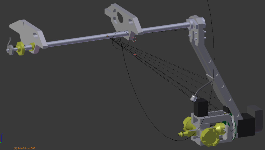
The voind robot arm rotates on a axle that would originally sit on a pair of plain plastic bushings.CAM00272_edit01

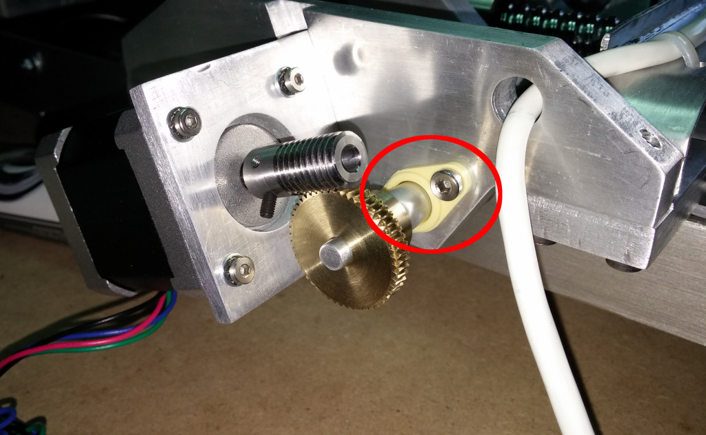
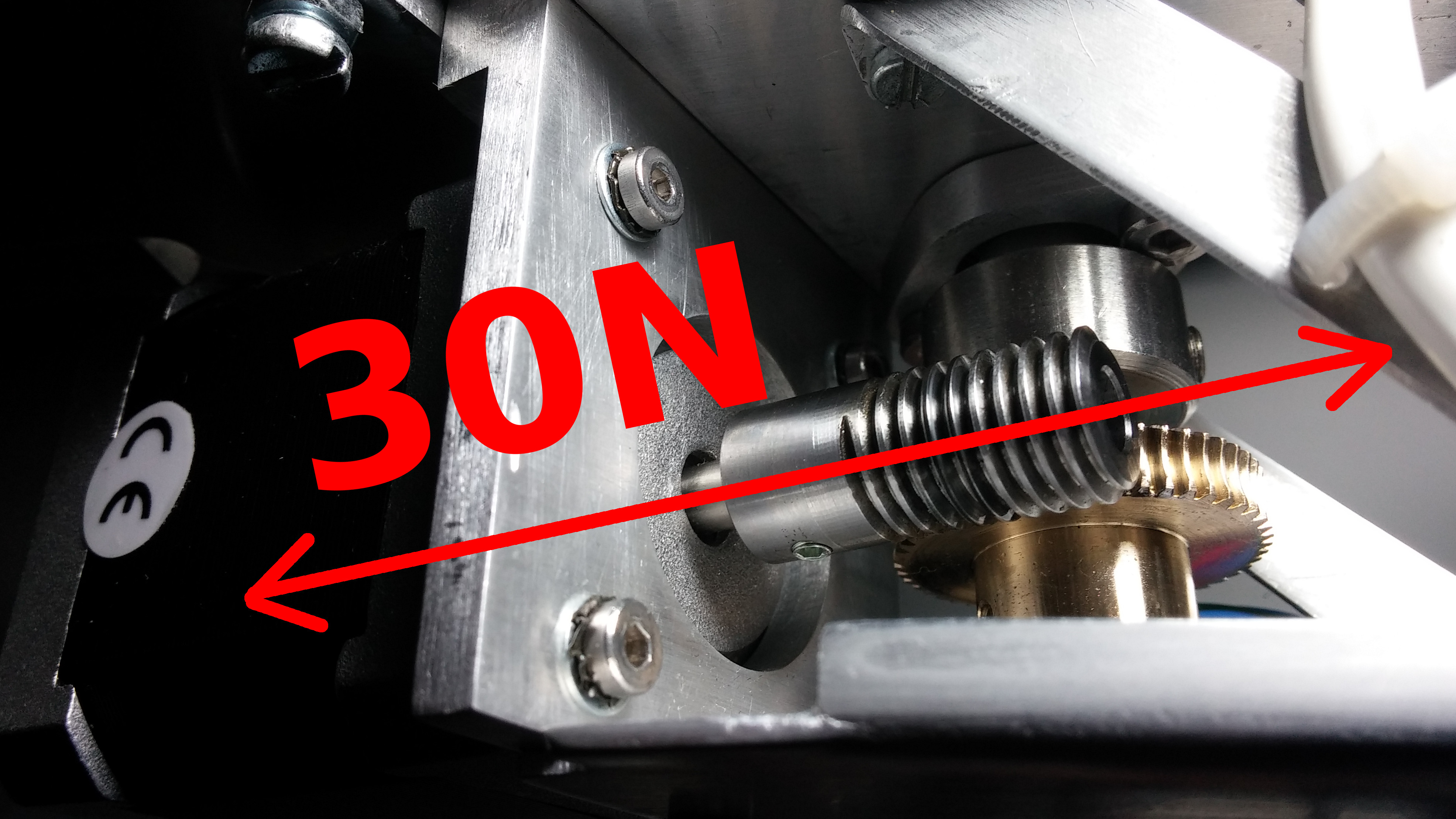
However, due to the lever effect of the arm’s weight pivoted on the rear bushing and the amount of play that these bushes naturally allow, this arrangement was causing noticeable play on the worm/wheel engagement which we feared would quickly wear out the gears. Additionally the lever effect was causing excessive load for the bushing which would cause further play.

ArmLever

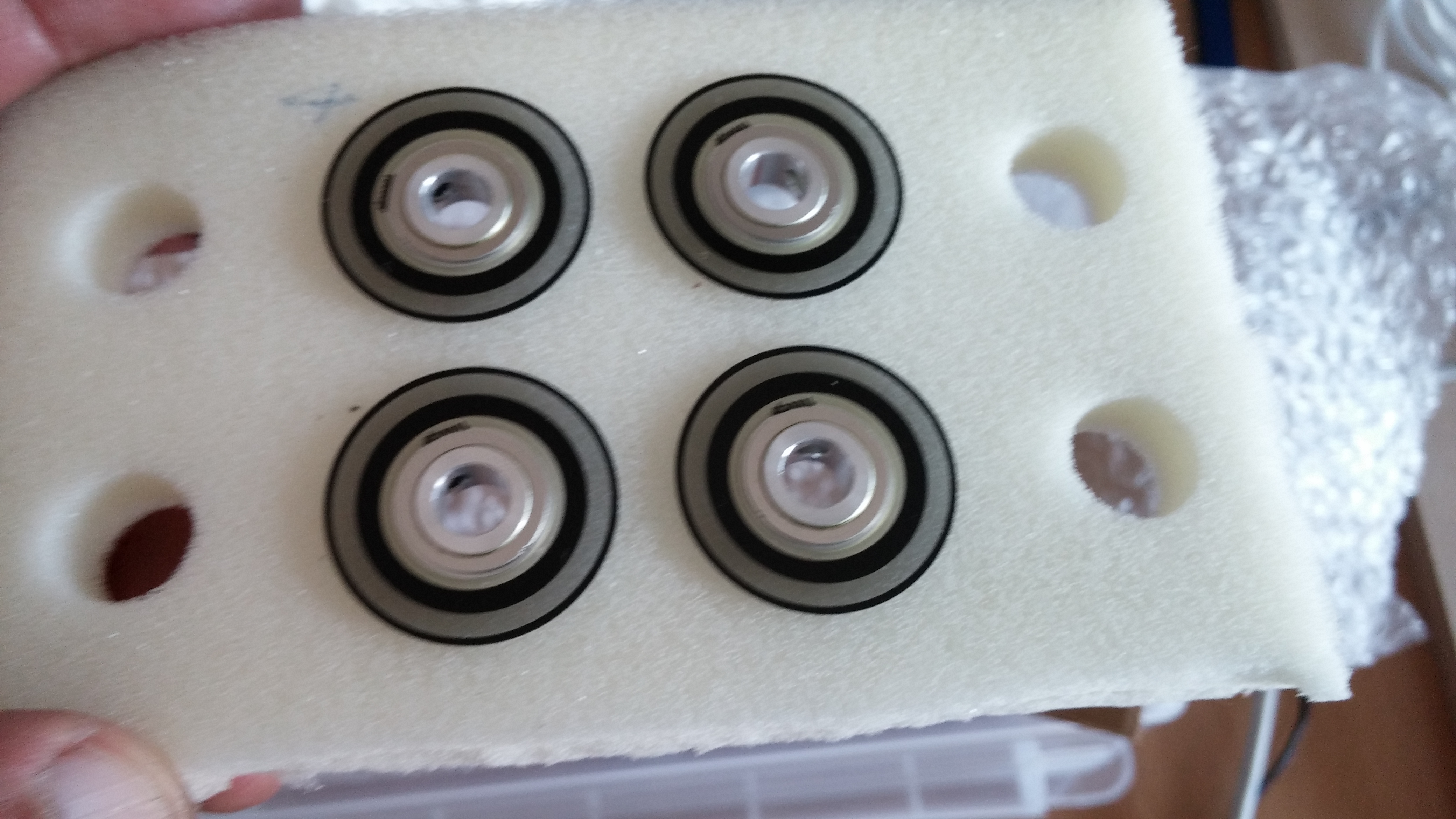
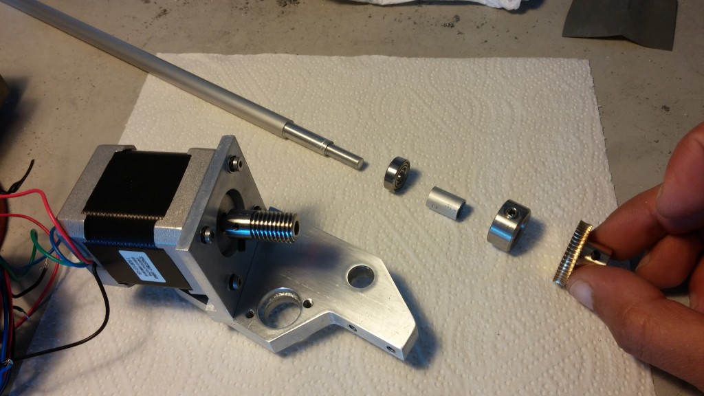
This problem was addressed by a) replacing the aluminum shaft with a steel one; b) replacing the plain plastic bushings with a pair of ball bearings;

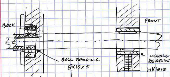
Using bearings would help to counteract the loads, achieve a more stable support for the shaft and bring the shaft play under control. We also went for an arrangement with a needle bearing at the front where most of the load is applied and a ball bearing at the back close to the worm/wheel.

ThetaAxleBearingArrangement_01

(bearings)

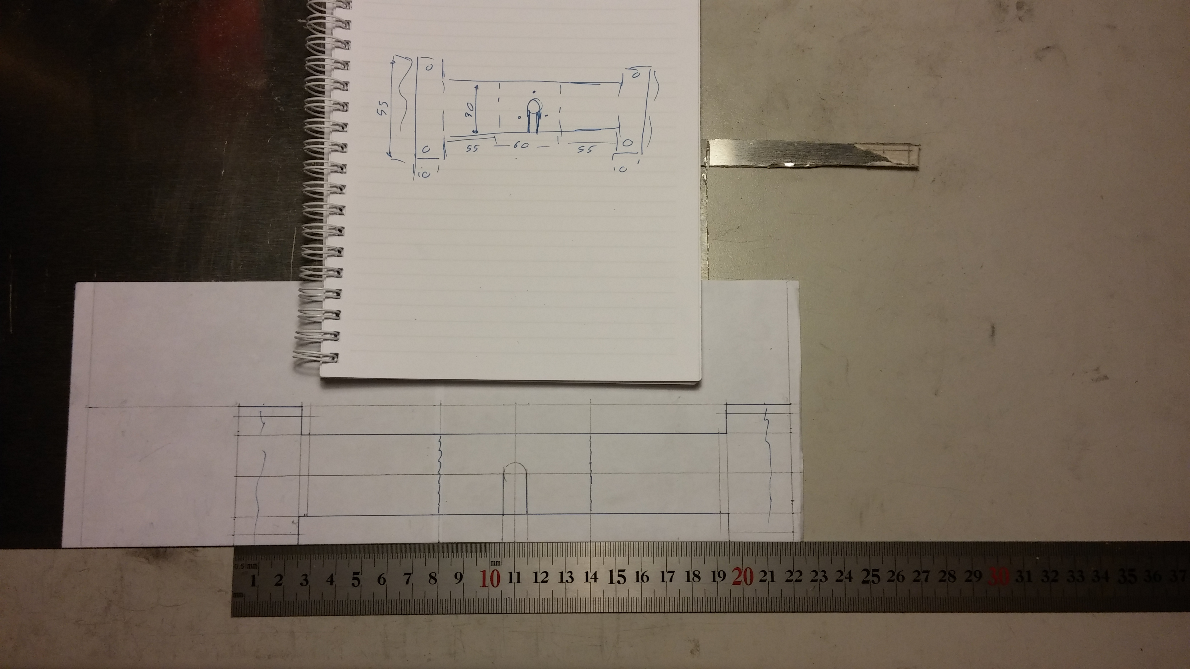
The first challenge was to rework the two aluminum parts to house the bearings. We also wanted to recycle the existing parts to save energy and time.

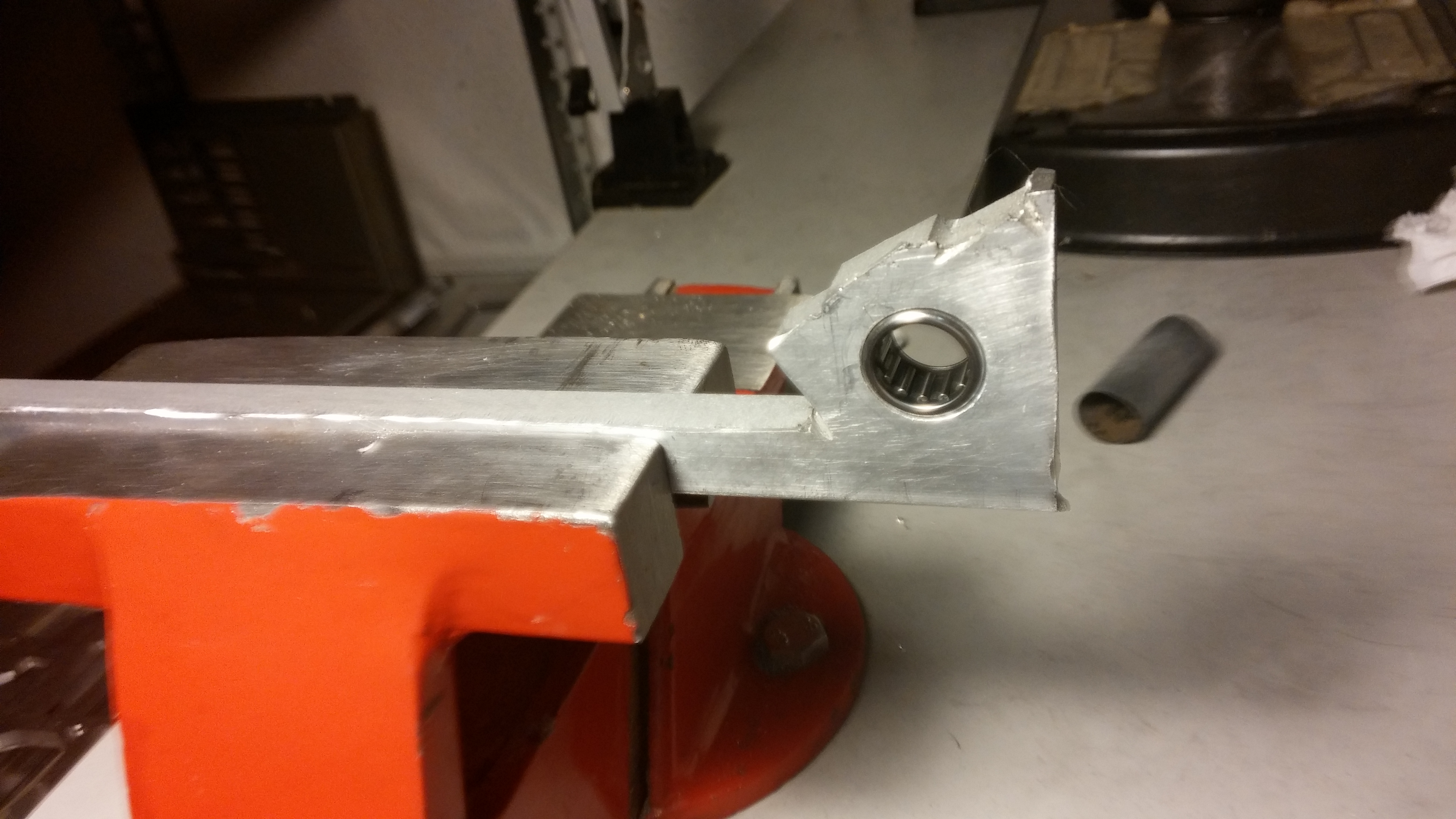
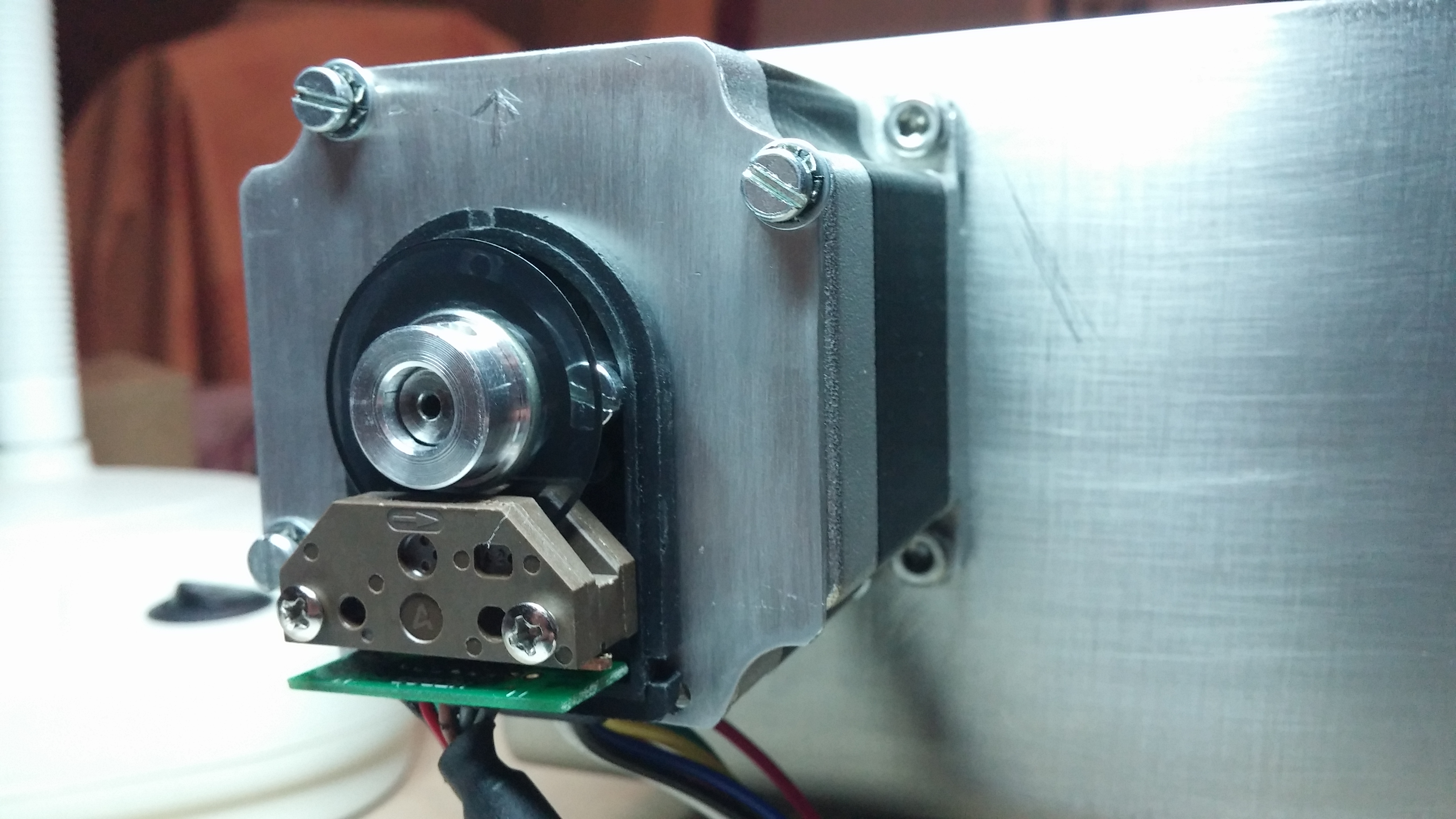
Fitting the needle bearing to the front part was simply a matter of enlarging the existing hole for 14mm, and using some sand paper to obtain a smooth surface and a tight fit. The bearing would be kept in place by a grub screw gently pressing against the outer ring.

Using a piece of aluminum scrap we were able to test this arrangement.

CAM00393

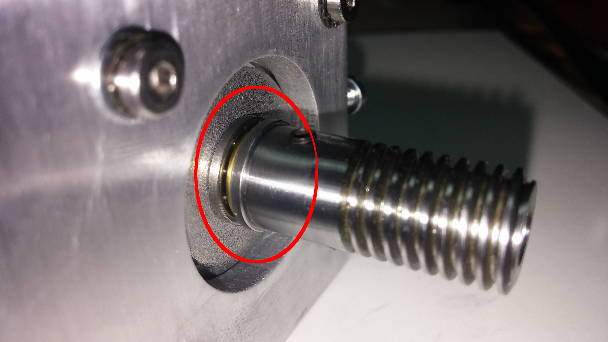
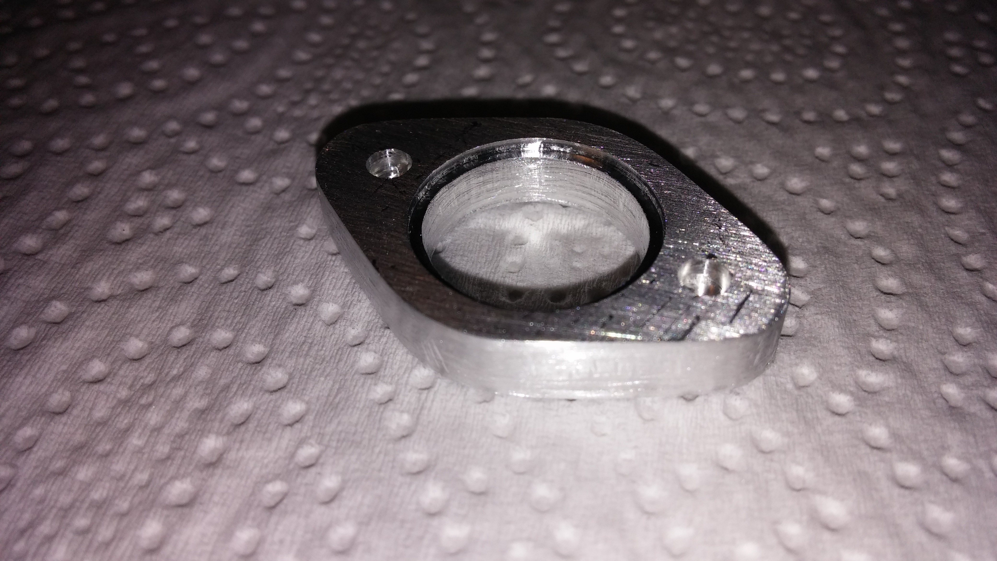
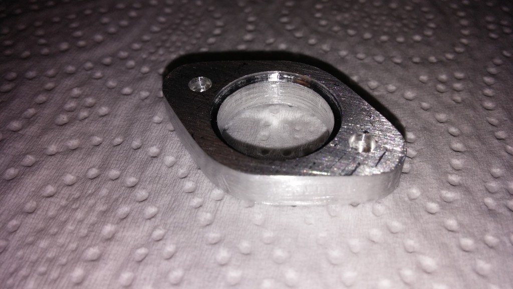
The rear bearing housing required some more thought. This bearing would support the axial load exerted by the end effector pressing perpendicularly to the equipment panel and would have to be properly fixed to counter this load. This meant that the housing would have two concentric holes: one trough the whole part with a 14mm diameter and another only half way with a 16mm diameter.

Machining a new part from scratch would make it easy to accurately cut this feature into the part, while machining the existing part would make it nearly impossible to align the part with the needed accuracy.

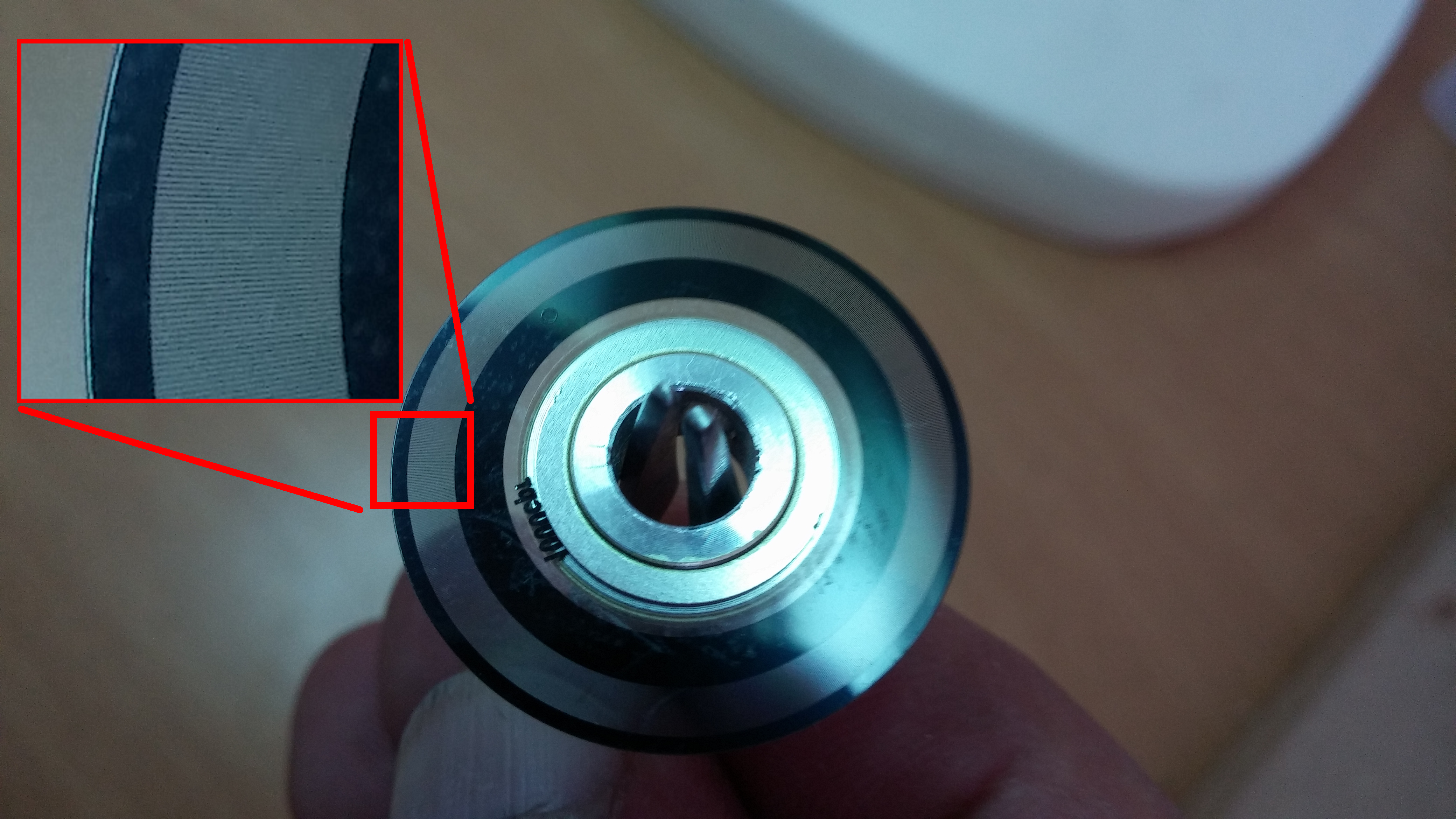
A third option was selected: drill a second 16mm hole halfway over the previously drilled 14mm hole. Using a drill with a 135º split point meant that instead of having an “horizontal” bearing surface we would have instead a truncated conical surface with a 22.5º inclination towards the center. While this might not be the ideal surface to support the bearing, the modest axial loads would still be under the values needed to start deforming the housing.ThetaAxleBearingArrangement_02

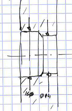
The two aluminum parts had to be carefully aligned and drilled in a single operation. This was further complicated by the fact that one of the parts already has three binding post screws protruding from it. CAM00410

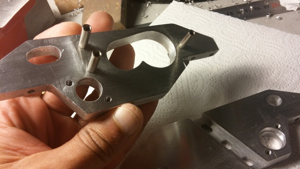
So a complicated fixing jig had to be arranged for this operation.CAM00404

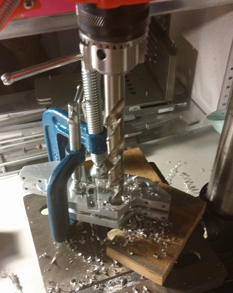
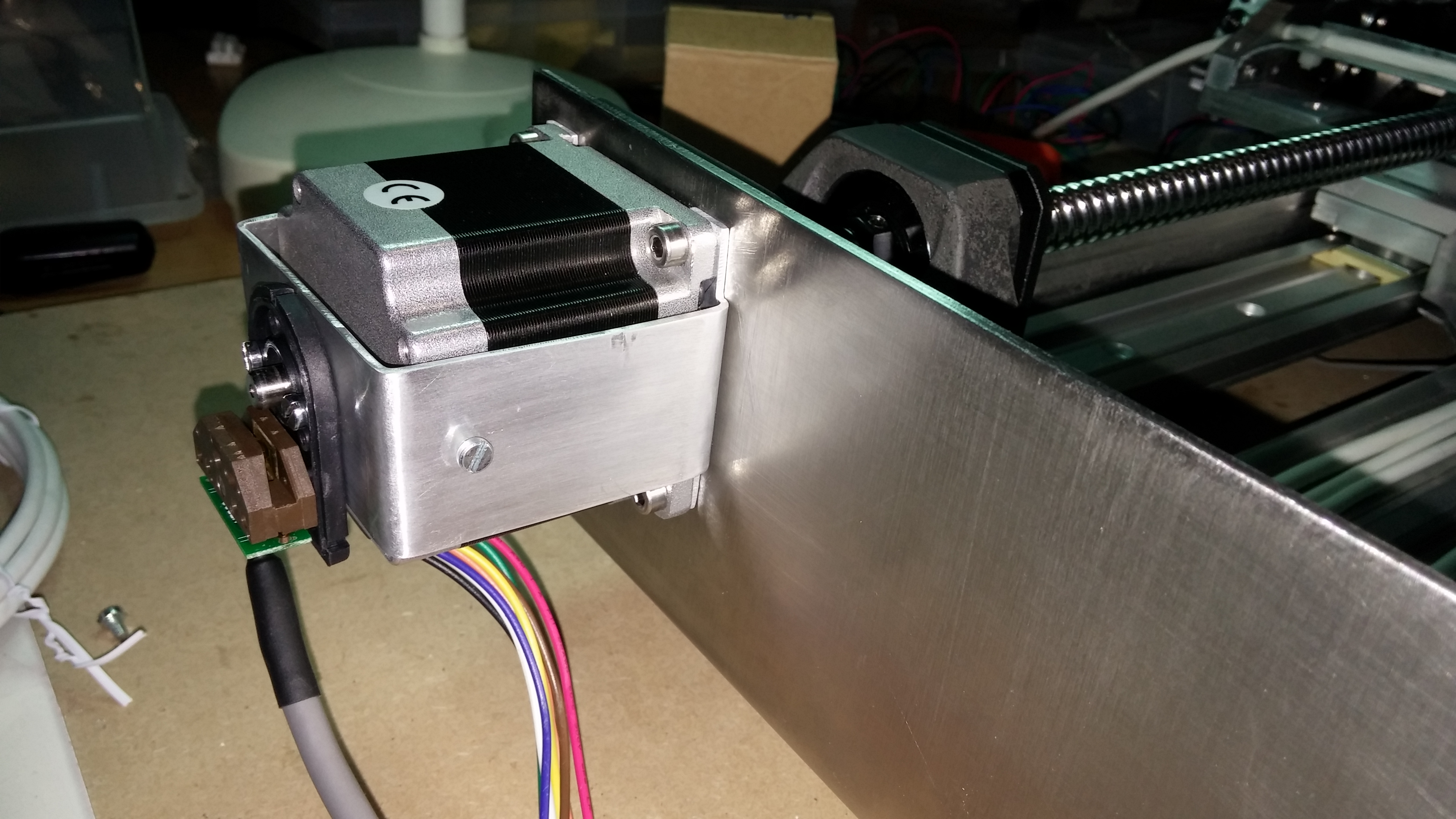
Finally we got the two parts ready to house the bearings.

CAM00413

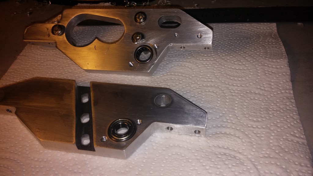
We machined an additional part which presses over the bearing and keeps it in place while resisting the main axial load.

CAM00006

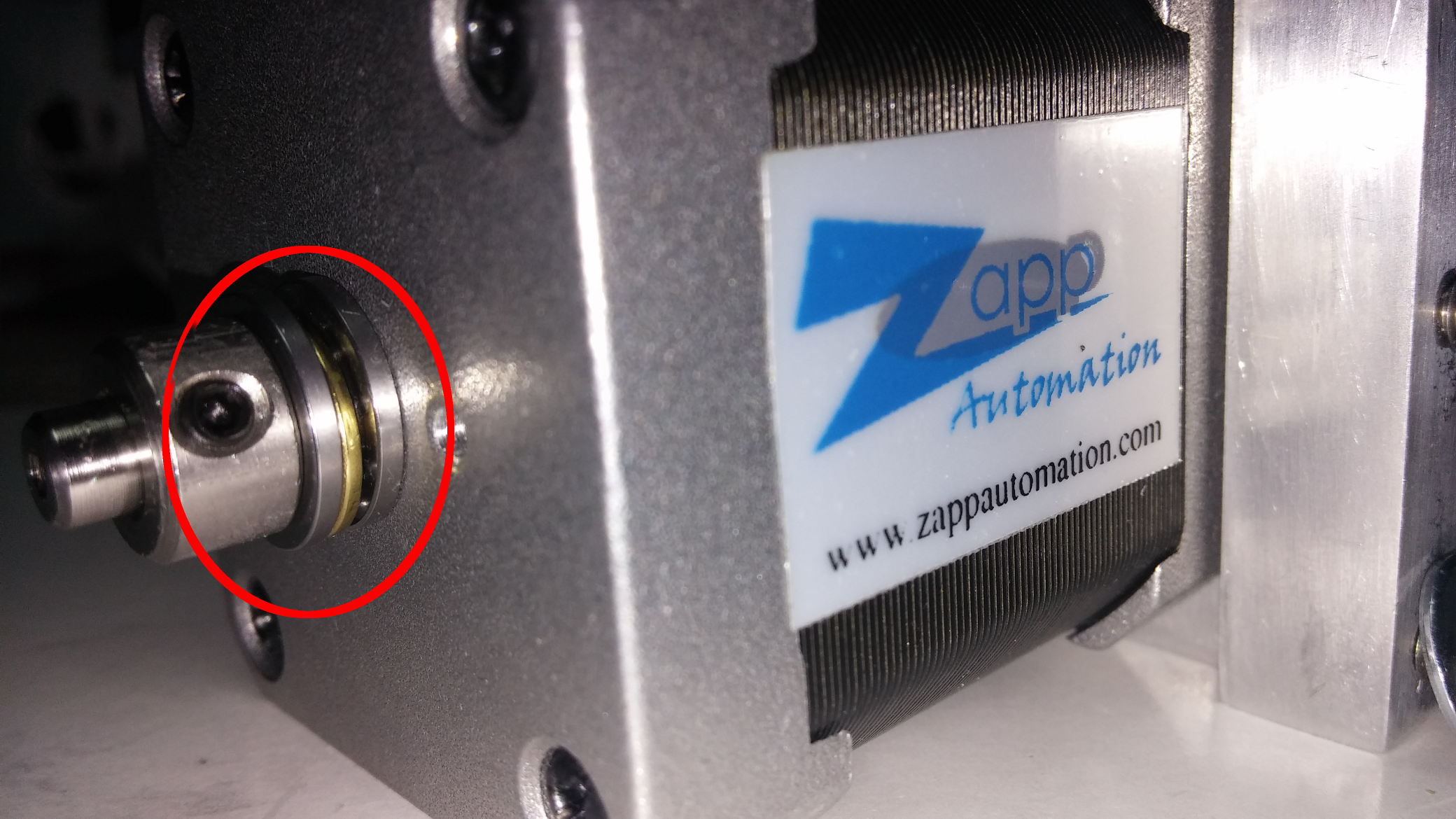
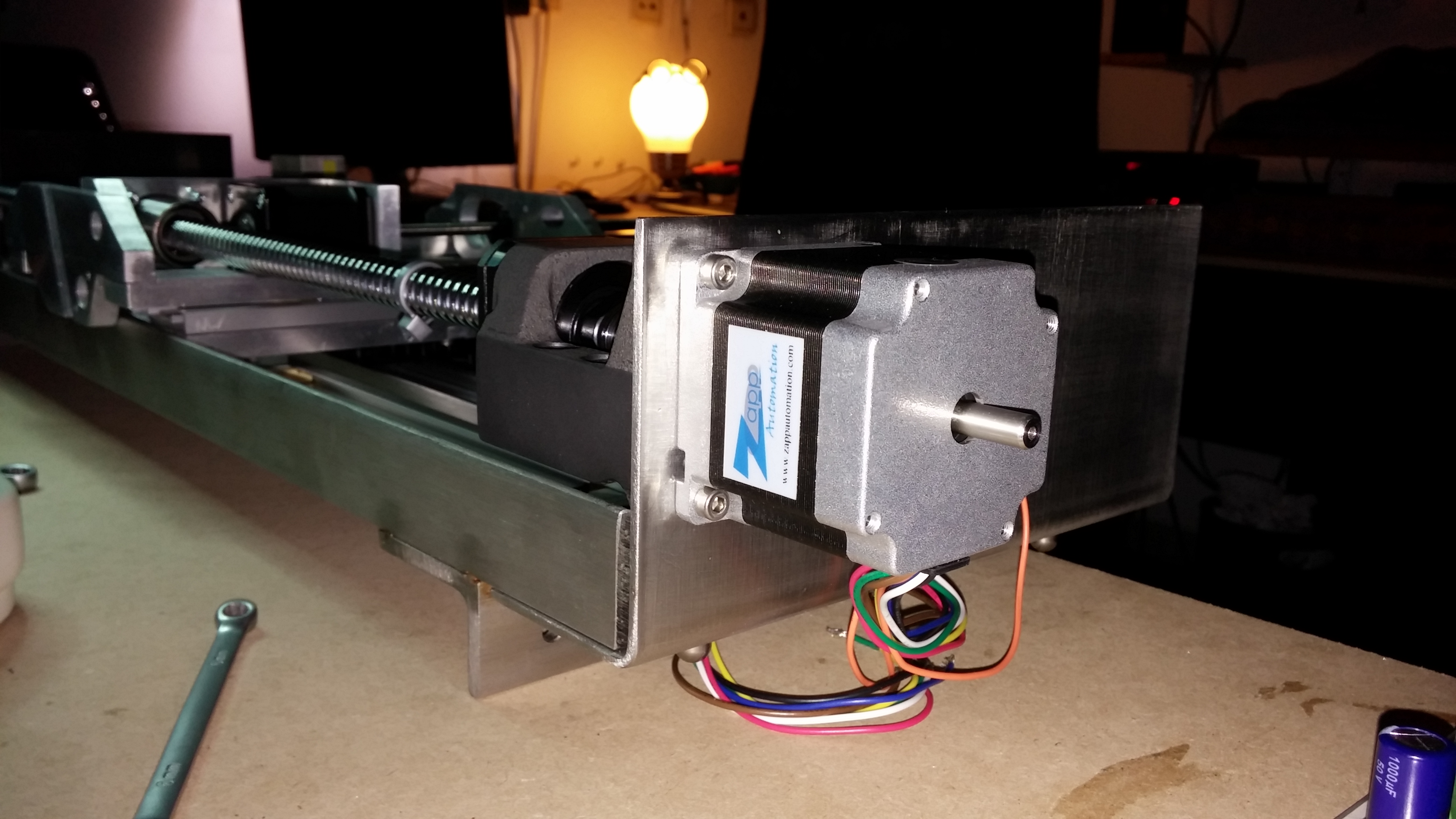
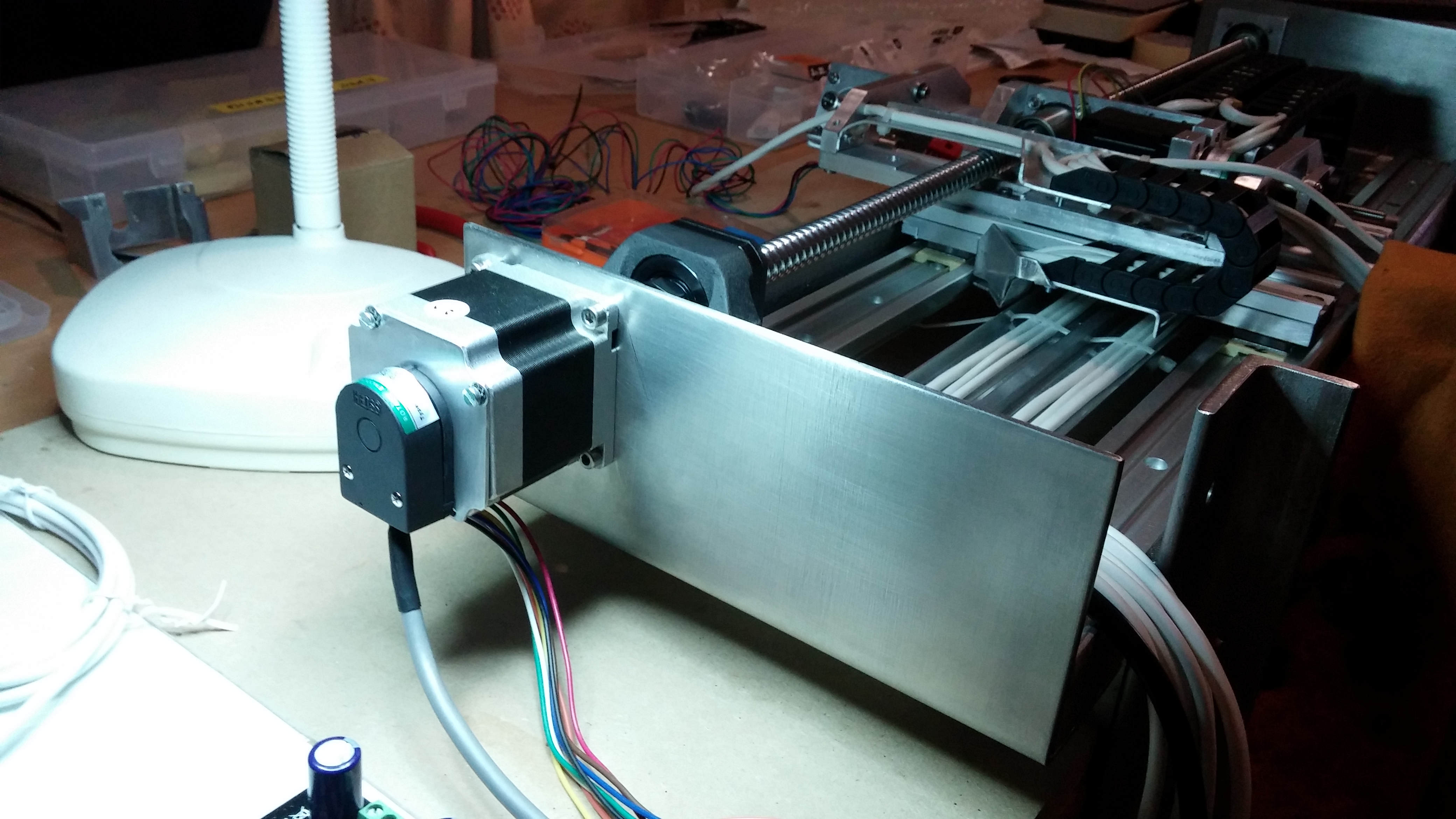
We then set up the assembly using the temporary aluminum shaft built with our DYI combined milling/Lathe machine.

CAM00417

Even with this temporary shaft and a damaged bearing (damaged during installation) we could immediately notice the improvement from using proper bearings.


Attaching an Encoder to a Stepper motor

The voind robot will use encoders to provide feedback on the position of 4 different axles. These optical encoders attach directly to the motor shaft and were supplied disassembled with the encoder disks carefully packaged inside a sheet of protective foam.

CAM00370

The encoder uses a mylar disk with the optical grid almost invisible to the naked eye. This component attaches directly to the motor shaft.CAM00371_detail

The motor producing the movement on the X direction was the first to have its encoder attached. However, unlike some other motors which already have mounting holes for encoders, this particular motor required an additional arrangement to securely attach the encoder.

CAM00015

An option would be to drill very shallow (2-3mm) mounting holes on the motor backplate hoping that these holes would not damage the motor. However I was not able to determine if the backplate was sufficiently thick to drill a hole without ruining the motor.

The first option was to build a bracket using aluminum sheet that would be secured at the front of the motor using the existing mounting screws and extend to the back of the motor to provide the mounting point for the encoder.

CAM00350

Two bolts would prevent it from moving sideways and provide additional adjustment.

CAM00357

This design had however a fatal flaw: the encoder needs at least 13.5 mm of shaft to properly attach the encoder wheel. This arrangement would let only 8mm of shaft exposed. The part could be redesigned to sit more closely to the motor backplate, giving the extra shaft exposure needed.

We decided to try something simpler: using the very shallow M3 threaded holes on the motor backplate to fix an adapter plate to which the encoder would then be attached. The challenge here was to fix the adapter plate using only 2mm of thread engagement and at the same time providing M3 threaded holes to fix the encoder, all this on 1.8 aluminum sheet.

CAM00366

This arrangement proved to be adequate for fixing the encoder.

CAM00375

After a final cleaning to remove the dust particles that were sitting on the disk, the encoder cover was screwed in.

CAM00378