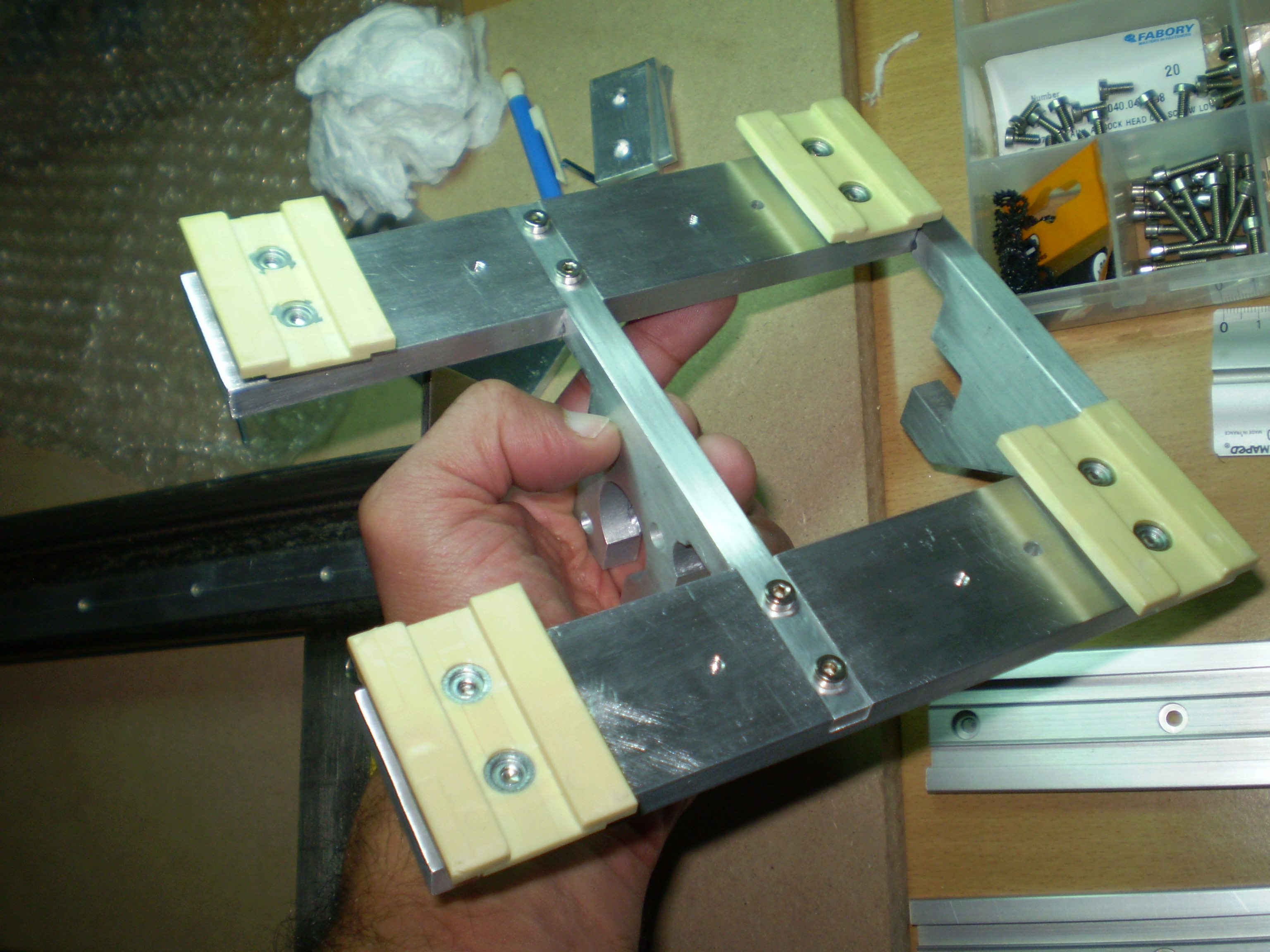
This was the first time we ventured into aluminum fabrication using a CNC milling machine. The majority of the voind robot parts were designed to be fabricated from aluminum bar using a CNC milling machine.
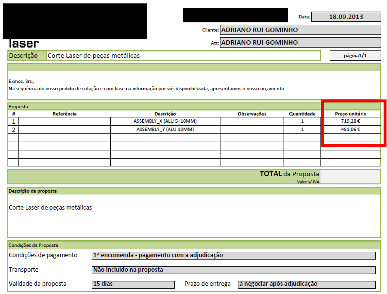
Soon into the project we realized how expensive it would be to have these parts sourced from specialized shops. We were quoted with hundreds of euros for a single aluminum part and we would need to fabricate more than 20 different parts!
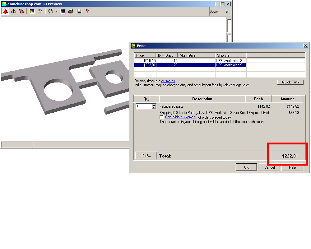
Online metal fabrication shops like eMachineShop were also evaluated but were still too far outside our budget.
Apart from this we feared we would end up doing several iterations before we obtained exactly the required part, specially because we lacked the knowledge and experience to spec the parts correctly.
So we decided to try and do it ourselves all the way from the 3d files up to the actual part machining.
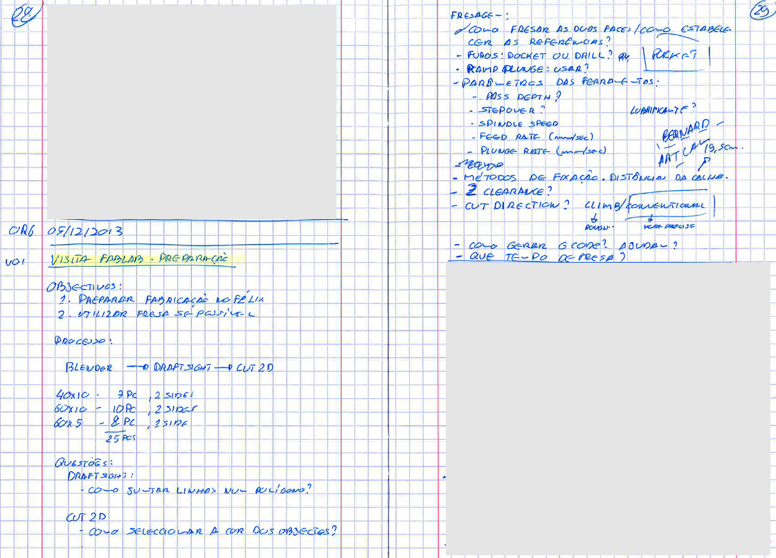
We started by visiting a local fablab shop where we met knowledgeable people who introduced us to the basic tools and techniques used to create the parts drawing files and prepare them to be submitted to the milling machine.
Unfortunately this particular fablab shop had their milling machine already booked for the dates we planned. However they kindly introduced us to another fablab shop where we could book the milling machine for specific dates which were compatible with our calendar.
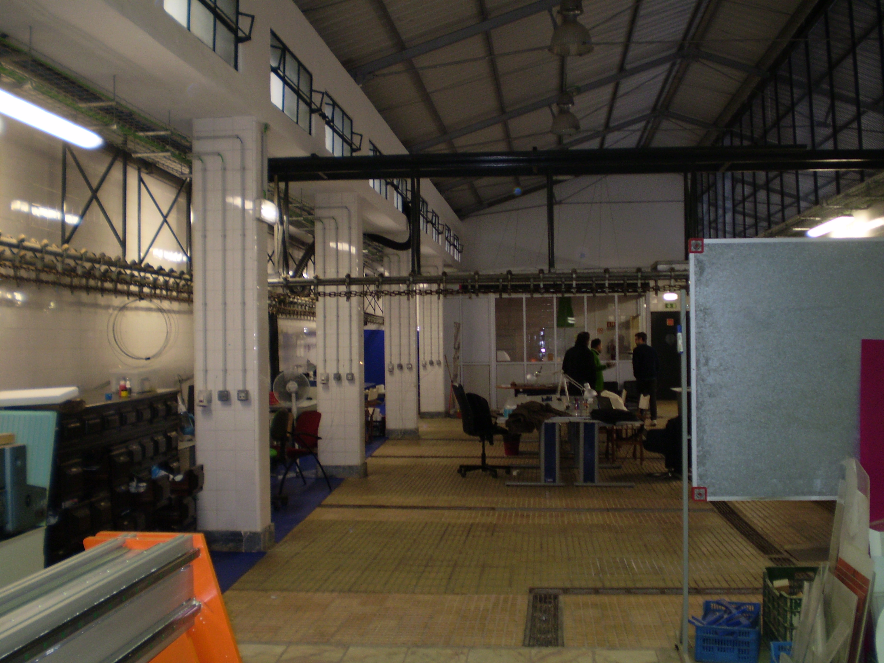
Isn’t it wonderful to have access to such an array of resources, tools and knowledge?
If you happen to have a project or idea and you are stuck with how to realize the physical aspect of it, search for the closest fablab and pay them a visit.
Mills and Milling parameters
After several broken mills we set on 3mm HSS + 8% CO end mills:
- Spindle: 5500 rpm
- Feed rate: 5mm/s
- Stepover: 1.2mm
- Stepdown: 0.75mm
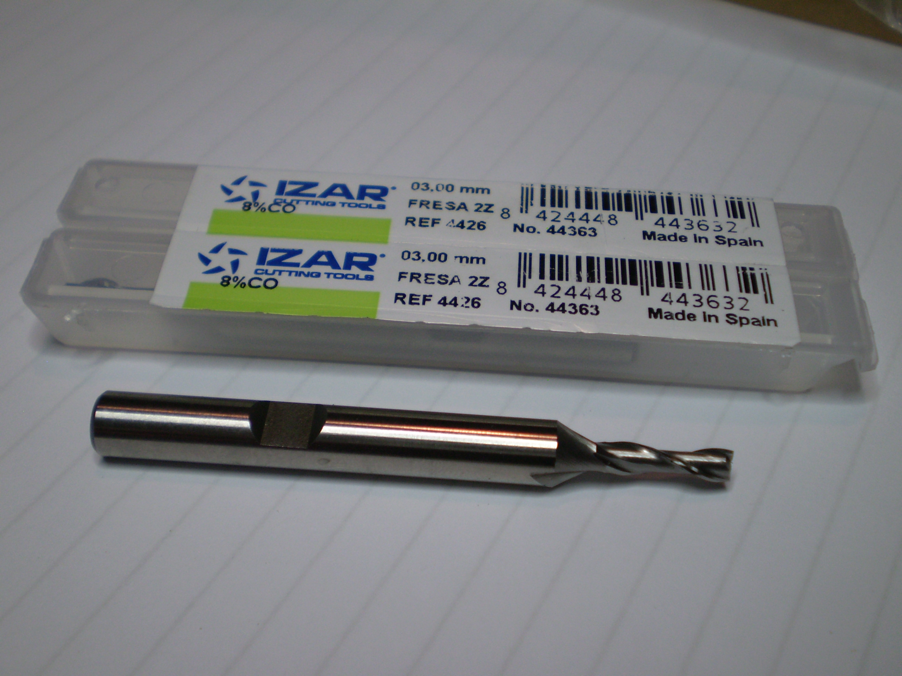
You can buy these mills from your local specialist tool shop. I bought mine here and here.
Lubrication and cooling
During the milling operation we manually sprayed cutting lubricant and also water to cool things down, specially during the most aggressive phases of the cut, for example when the tool had to start a new cut into the material.
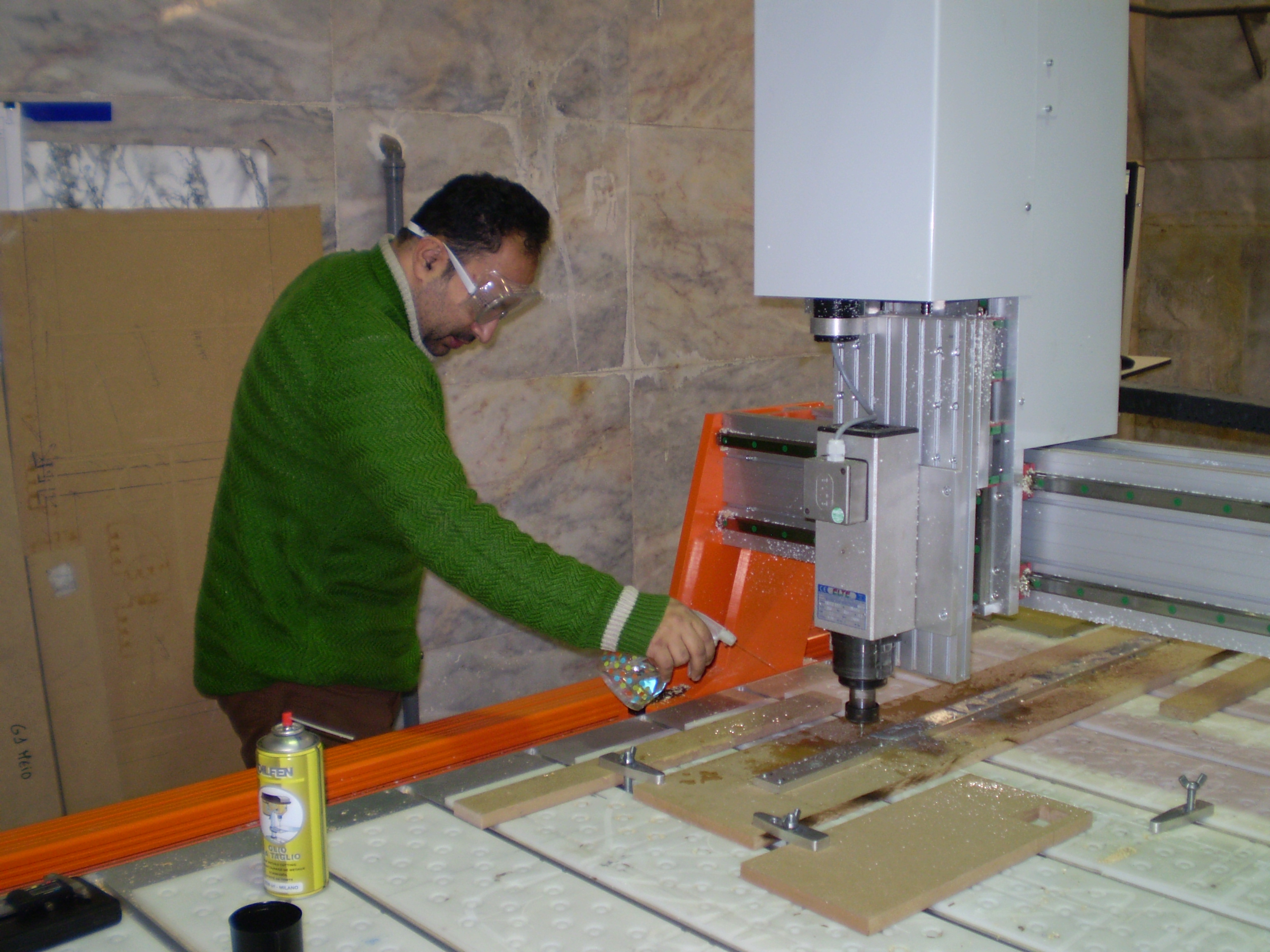
Sometimes we could feel the generated heat just by touching the aluminum up to 15 cm from the cutting action. The only time we tried to save on the lubricant and water we ended up with a mill literally welded to the aluminum. Not wanting to ruin another mill we diligently kept the spraying action throughout the whole operation.
Material fixing
We used MDF as sacrifice boards on which we fixed the aluminum bars using screws. The exact positions of the fixing screws were determined during the layout of the files in preparation for the milling operations. This way we could plan for an affective support of the material during the mill operation and at the same time check that the tool path would not touch any of the screws.
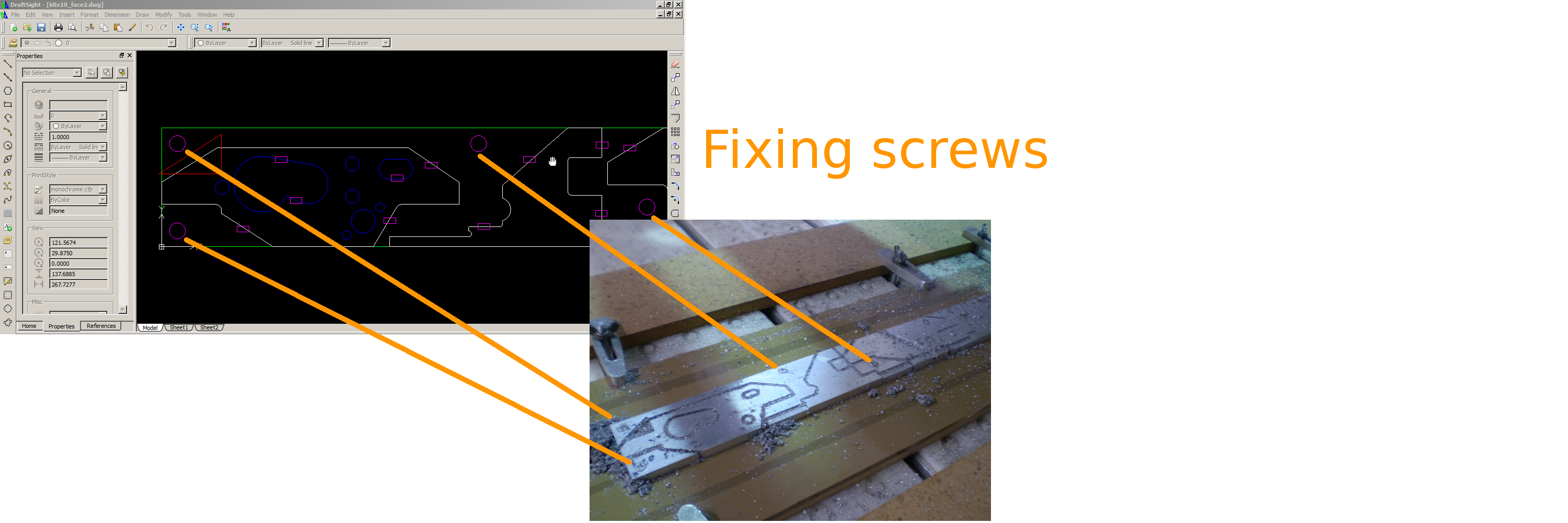
The MDF board was then securely fixed to the milling machine bed using additional MDF scrap boards and clamps.
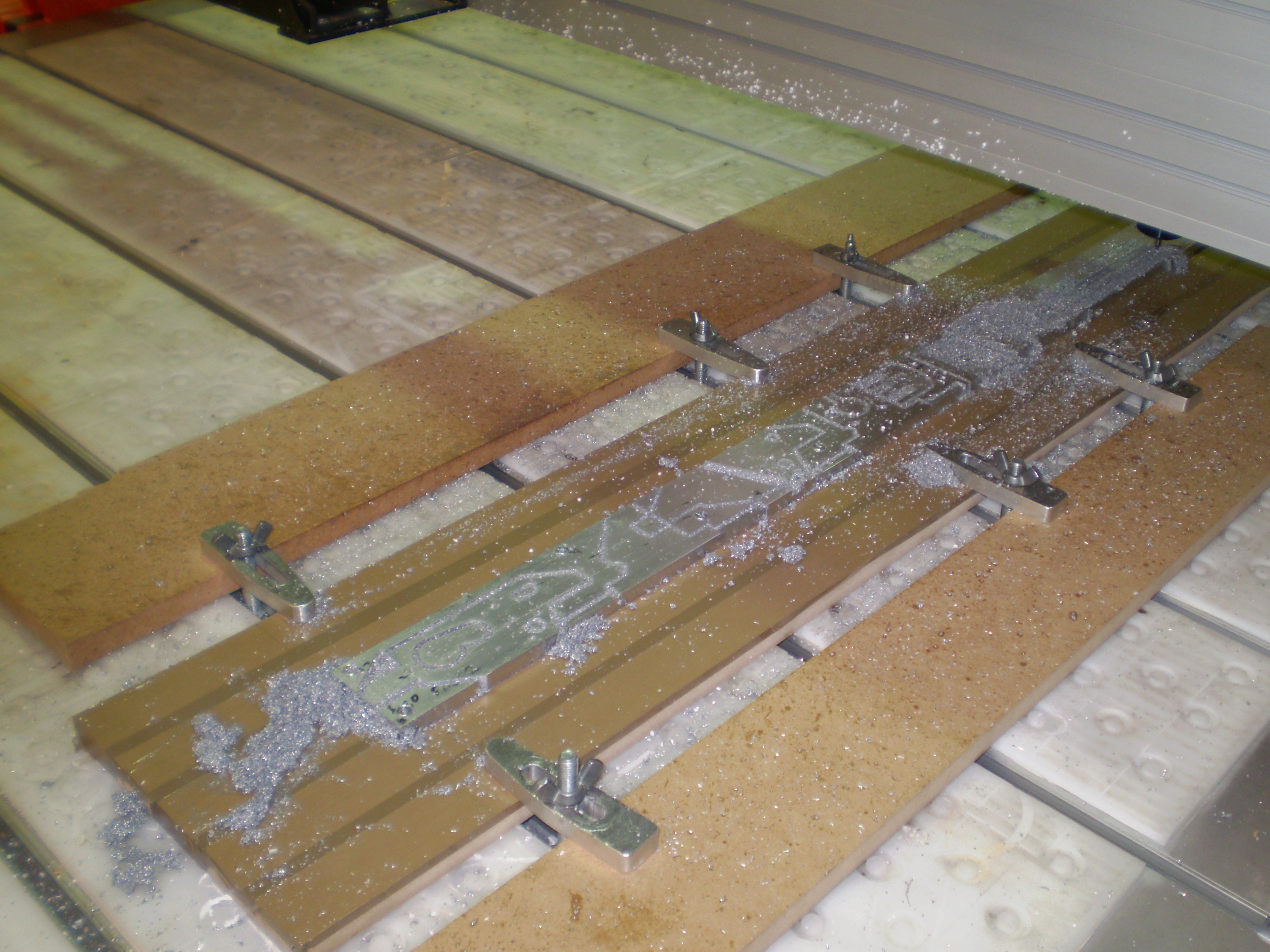
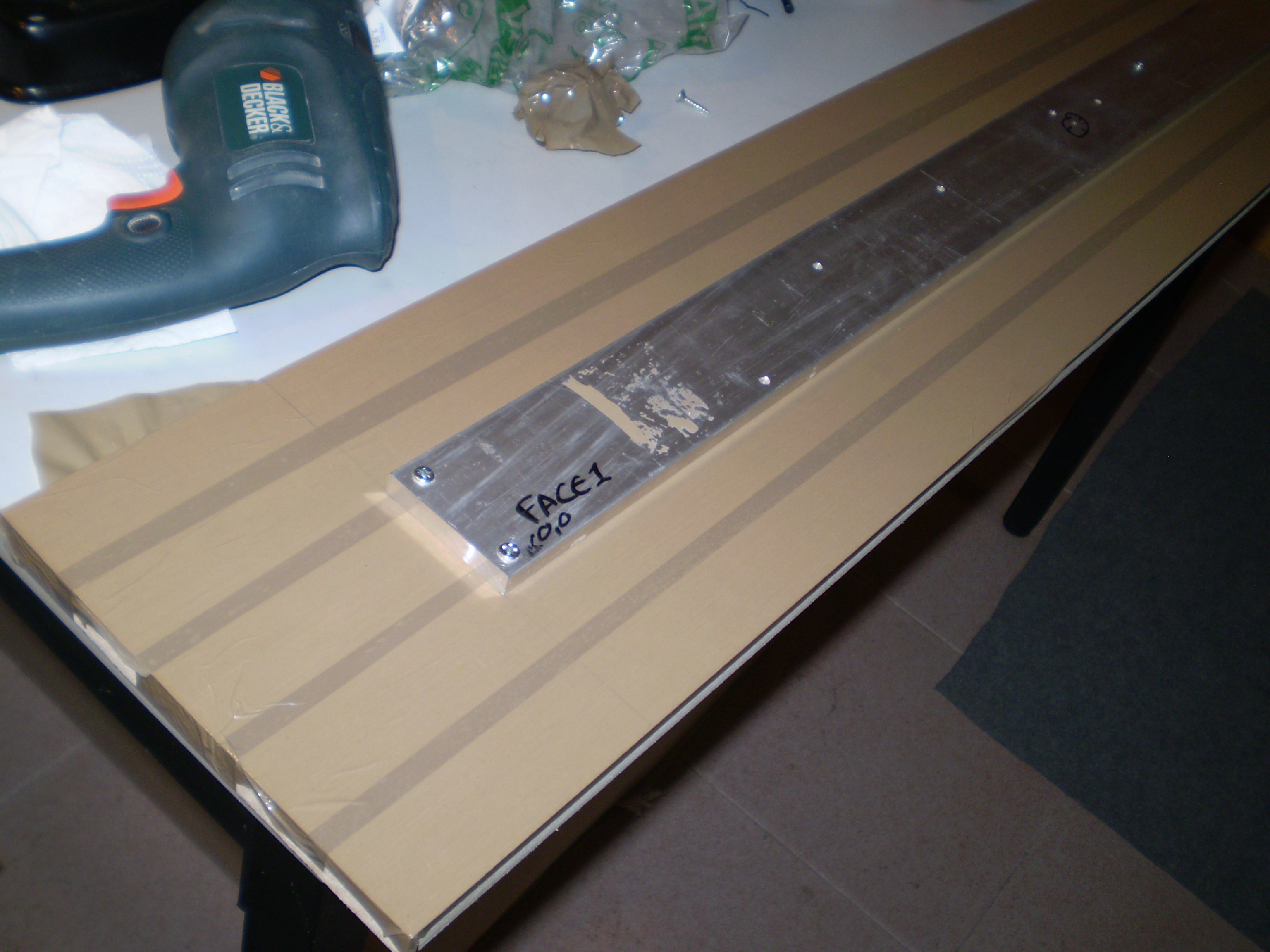
For long sequences of operations where the MDF board would be exposed for significant time to water and lubricant, we first covered the board and edges with adhesive tape.
However, any drilling operation that drilled into the MDF board acted as a direct injection point of water into the MDF causing it to swell and slightly push the aluminum up, enough to ruin all accuracy in the Z dimension. This led to some ruined parts and on two occasions left parts dangerously loose due to overshooting the cuts in the z axle.
The software we used to create the toolpaths did not offer enough flexibility to let us specify where to place brigdes to hold the cut parts in place. As a result we decided to leave a half millimeter skin holding the parts and separated them afterwards.
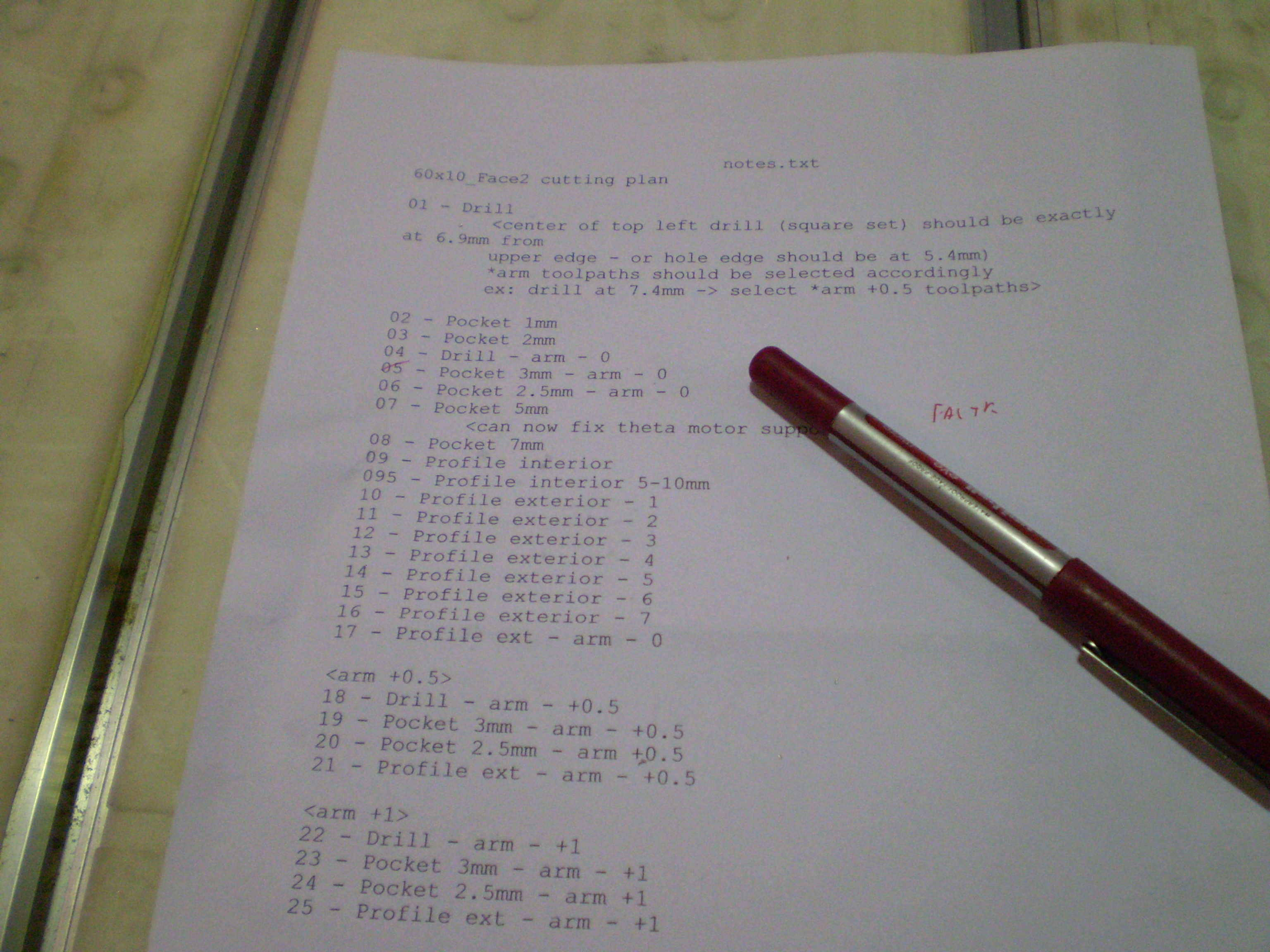
Workflow and Planning
The richness and openness of the environment at a fabrication shop like a fablab can quickly draw your focus away from your main objectives. There will be plenty of experiences to share and projects to admire and, unless you prepare yourself with a robust work plan, you might end up not using your time and available tools in the most efficient way.
Before a visit to the fabrication shop I usually try to:
- have a detailed plan for the tasks I want to execute;
- mentally rehearse and visualize all the tasks, the tools needed and all the contingencies which are likely to happen (like a broken mill, unavailable PCs, a corrupted file, etc.);
- prepare a checklist on the day before and make sure I am carrying everything I might need;
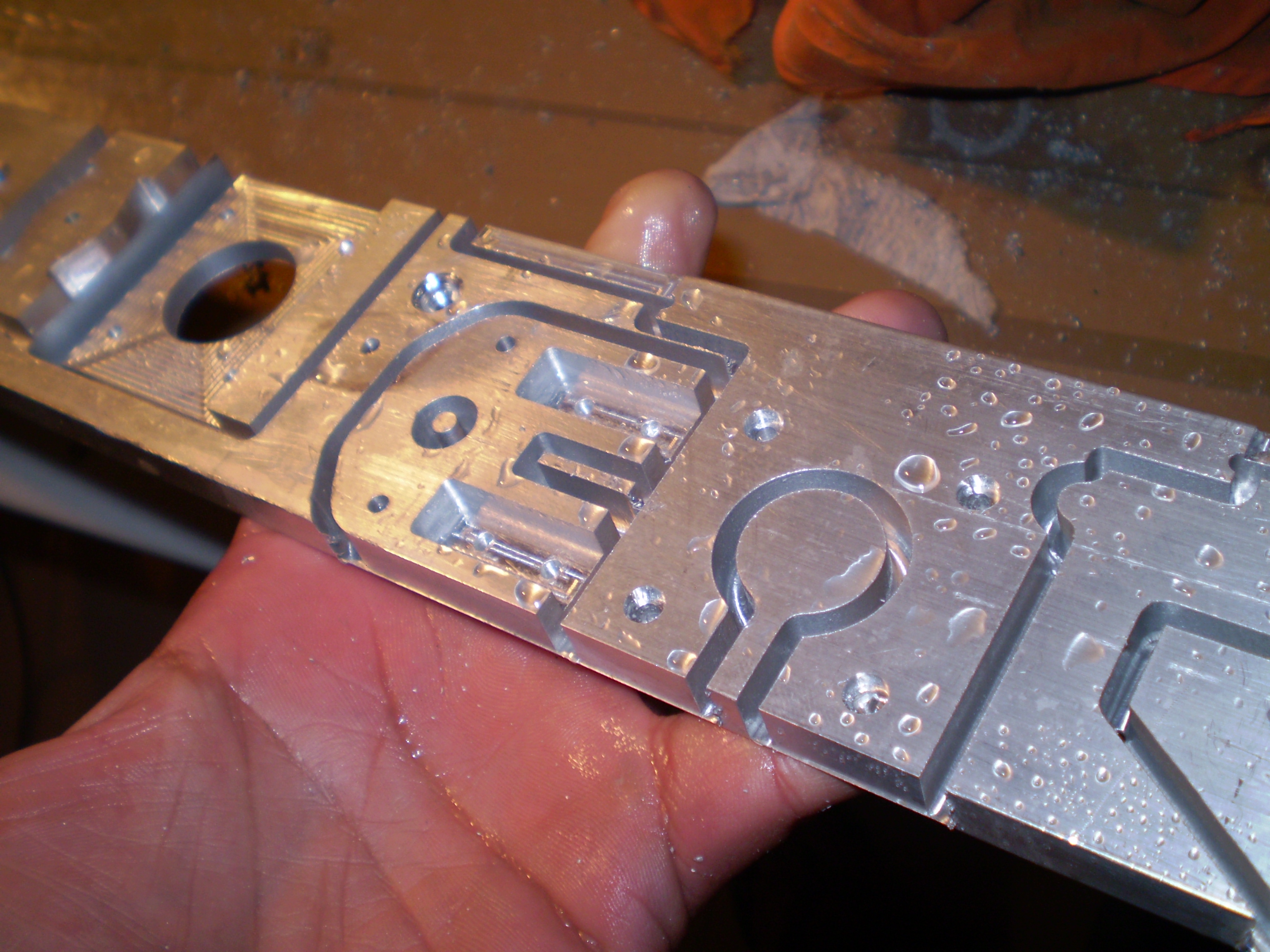
Finishing
Most of the times the freshly cut parts needed extensive finishing before being ready for assembly, specially because we insisted on leaving a half-millimeter thick “skin” at the bottom of the cuts to hold the parts together.
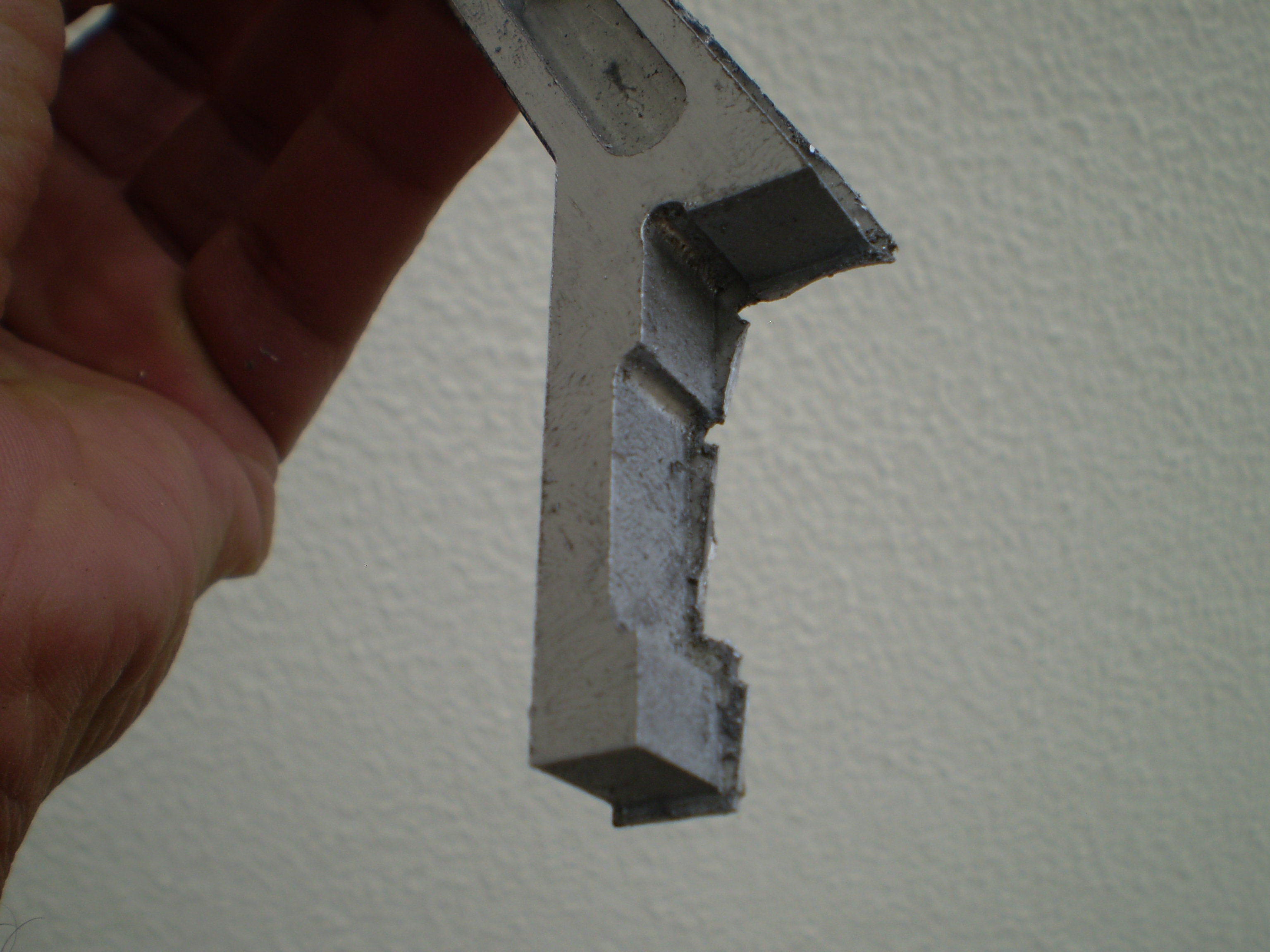
For that we used a Dremel and a mill tool to trim away the skin with the assistance of a steel guide to avoid cutting into the part. A final touch with a file and sand paper gave the part an acceptable finish to move it to the test assembly phases.

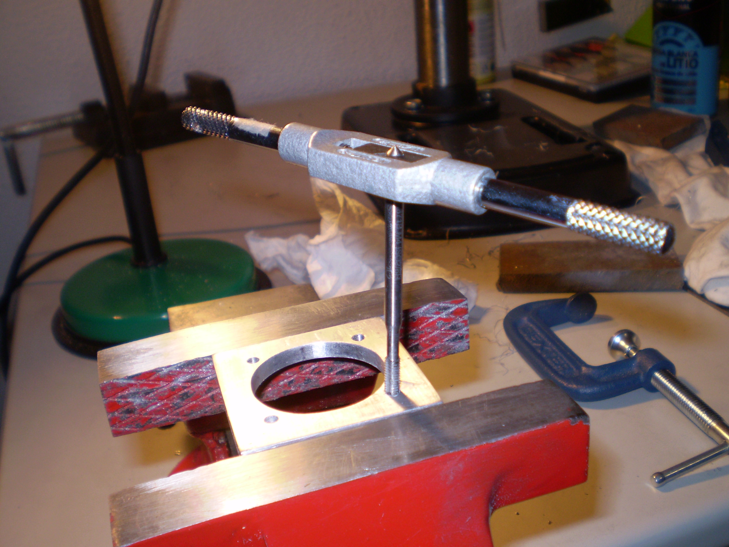
Fixing parts together
We looked for some time into the possibility of welding the aluminum parts. However due to design constraints which dictated that some assemblies would have to be disassembled for maintenance, we drill and tapped holes and used mostly DIN 7984 M4 screws to fix everything together.
Only time will tell if the joints are strong enough to withstand vibrations during normal operation.