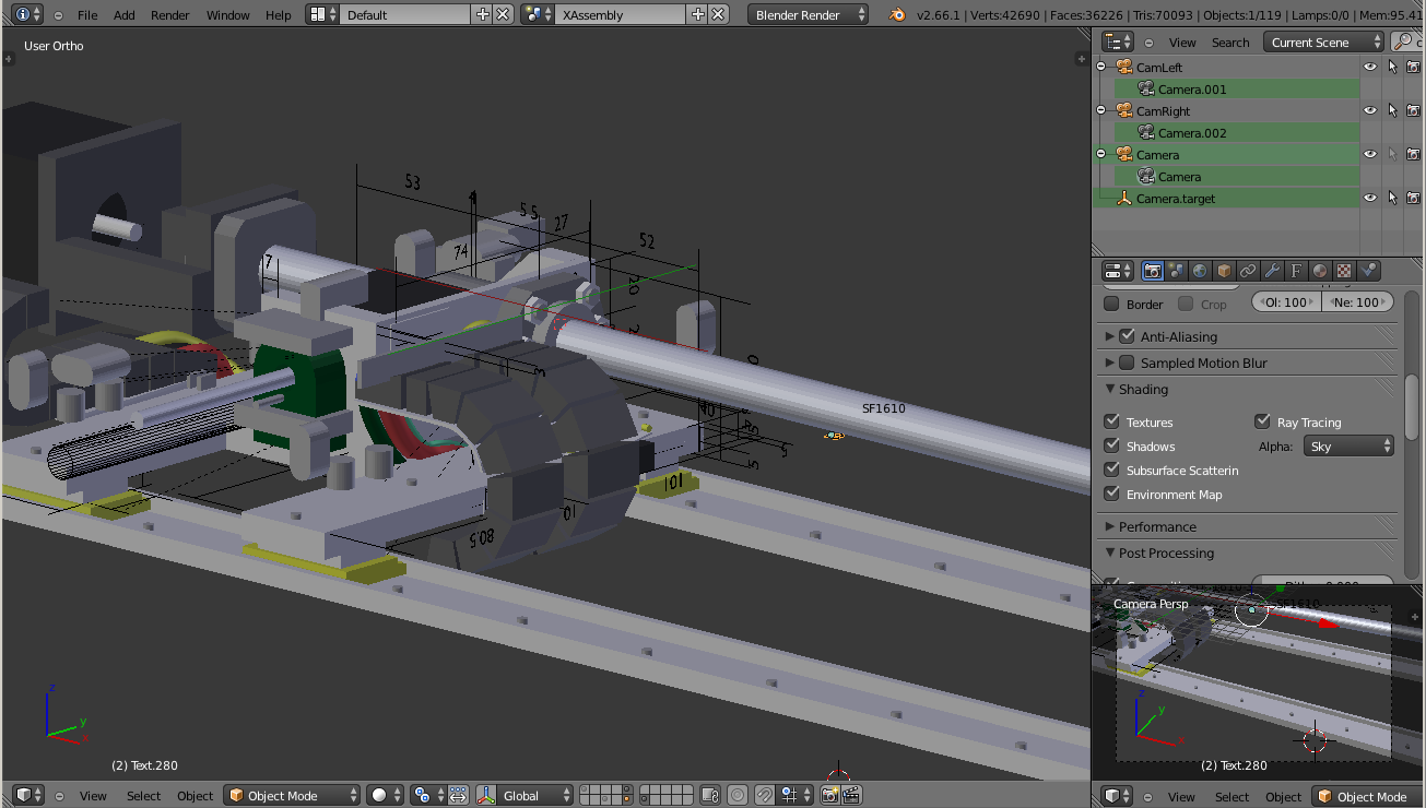
The voind robot concept was developed virtually in great detail even before a single part was produced, enabling us to work out the best arrangements to achieve a compact footprint (9 cm in height) for the sliding carriage assemblies. This part of the design was done using the excellent open source 3d design and animation package blender.
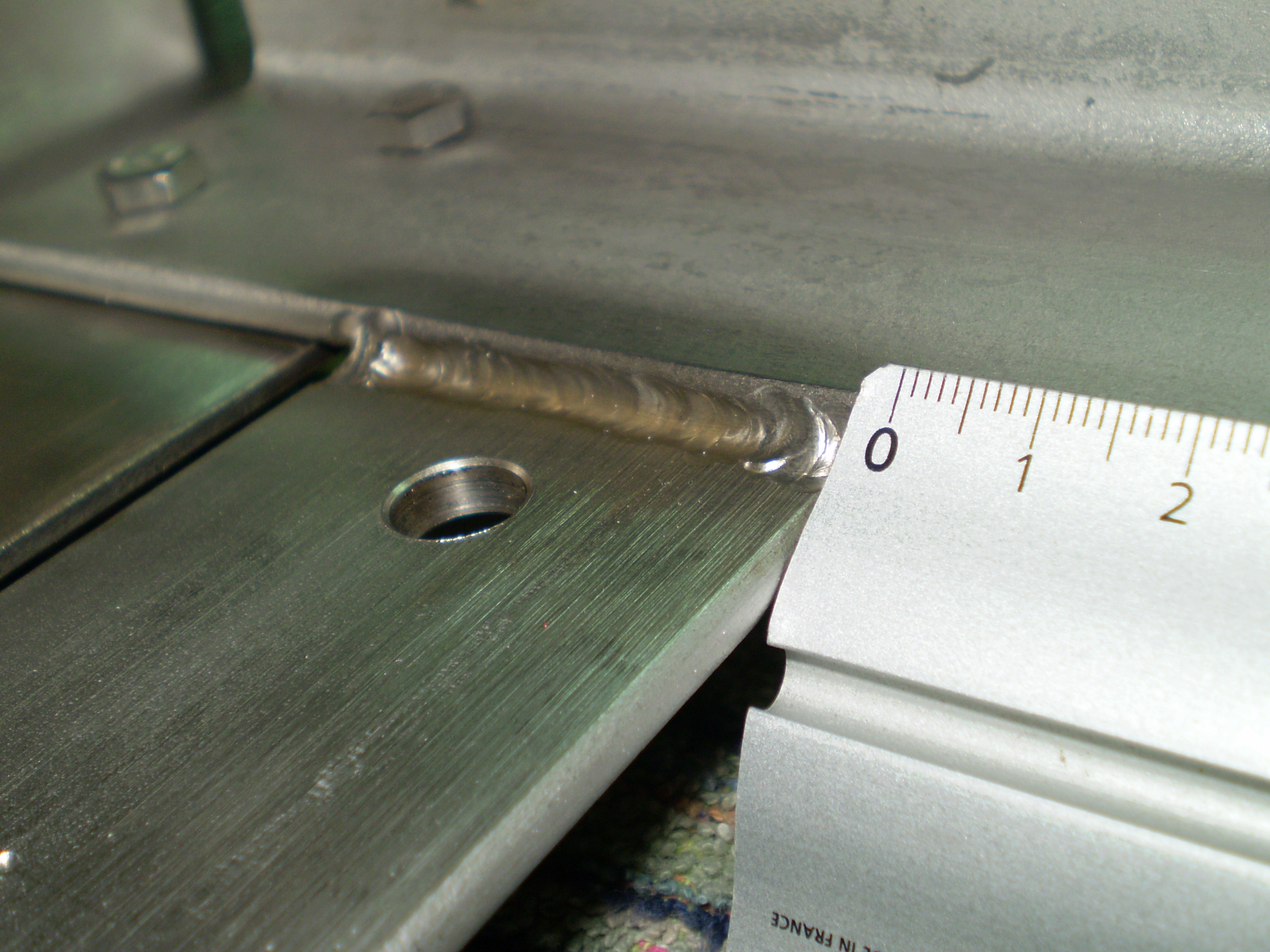
Once the overall chassis dimensions were established we produced the technical drawings and sourced the chassis fabrication and welding – stainless steel and tig welding.
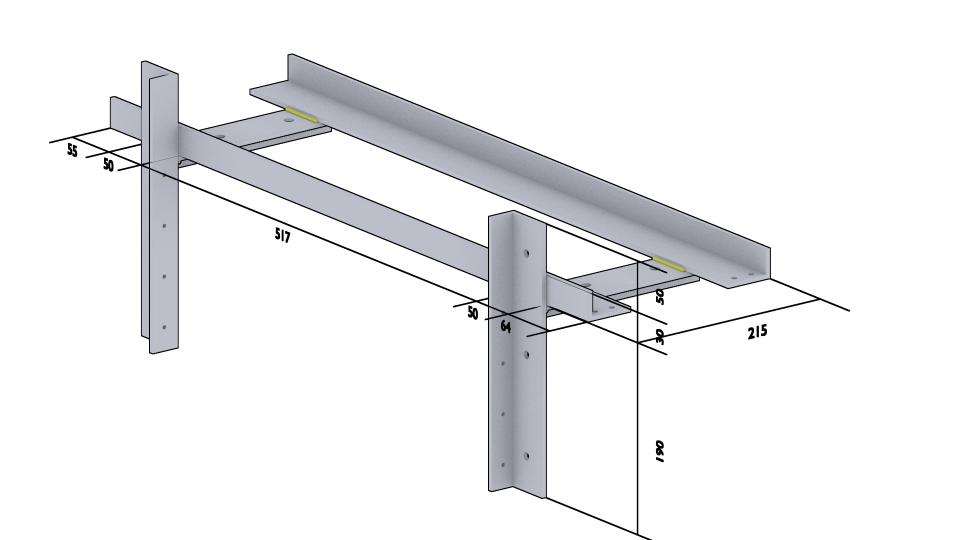
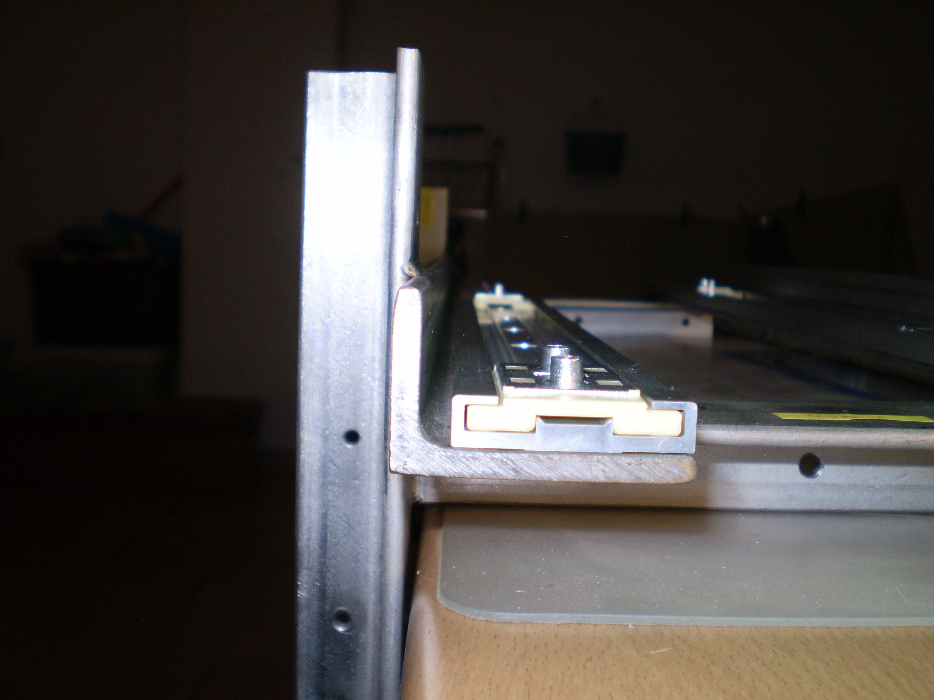
We chose to use a low profile linear guide system from igus, allowing us to fit the entire X-Y carriages and motors within a 90 mm height.
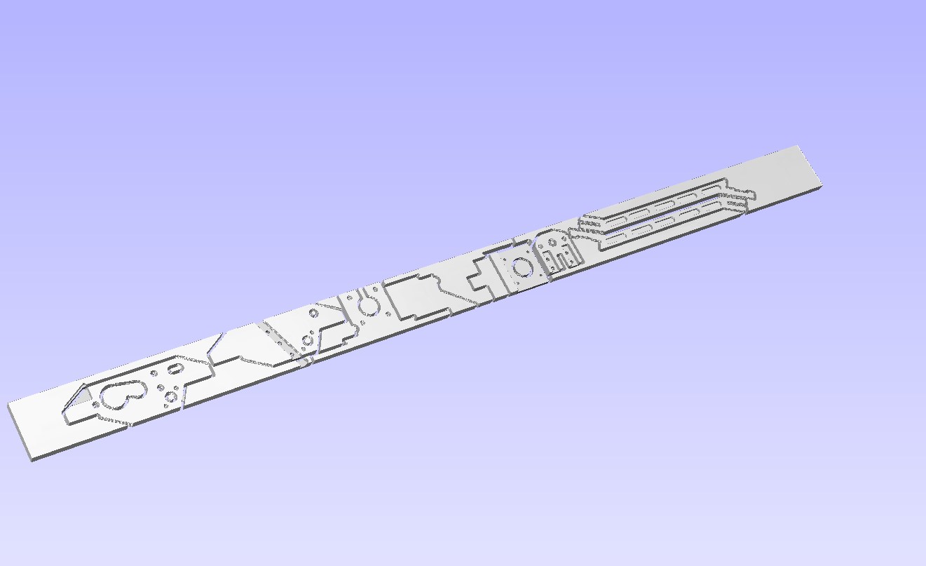
For the aluminum parts we produced the 2.5d drawings using DraftSight
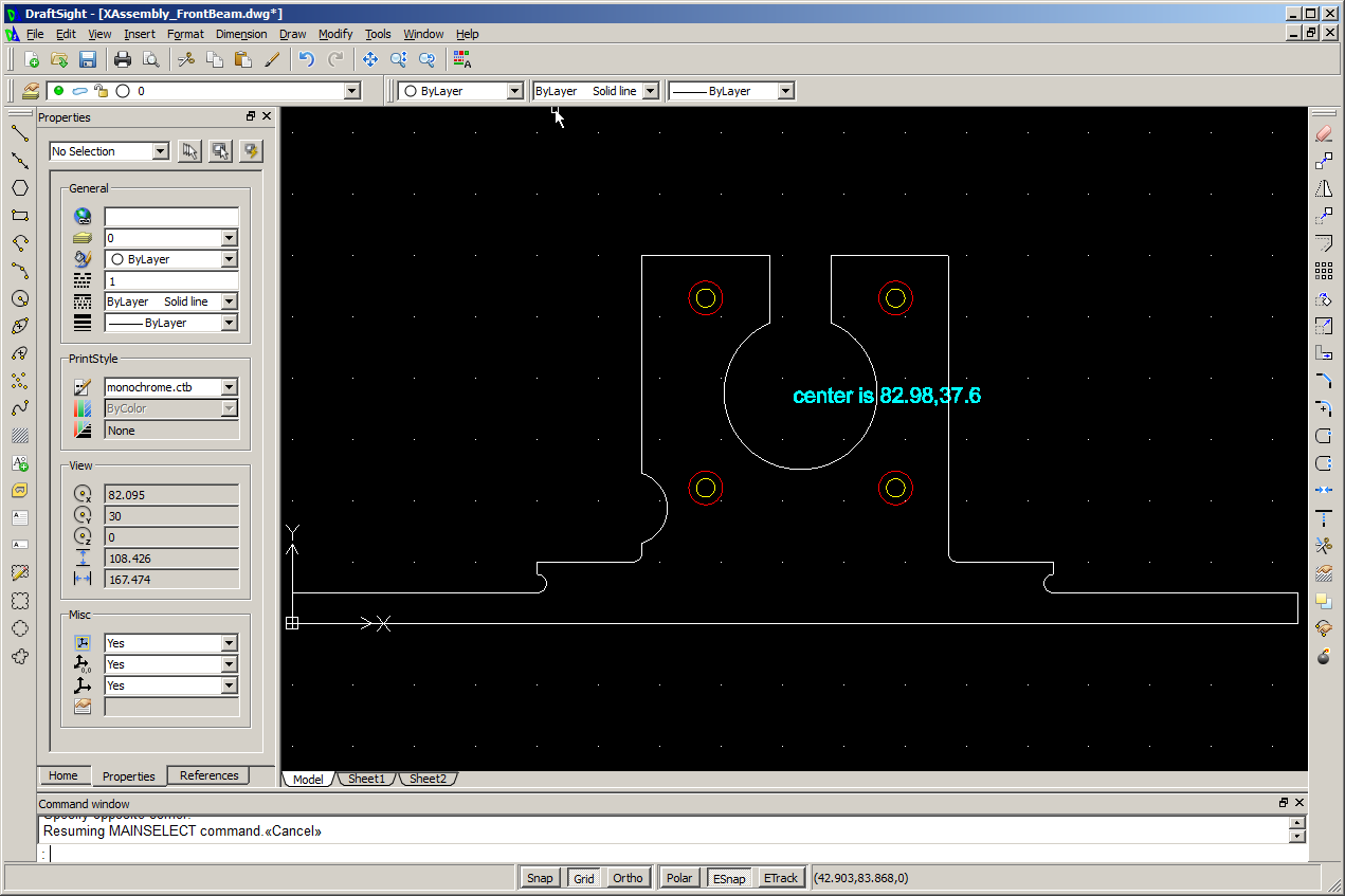
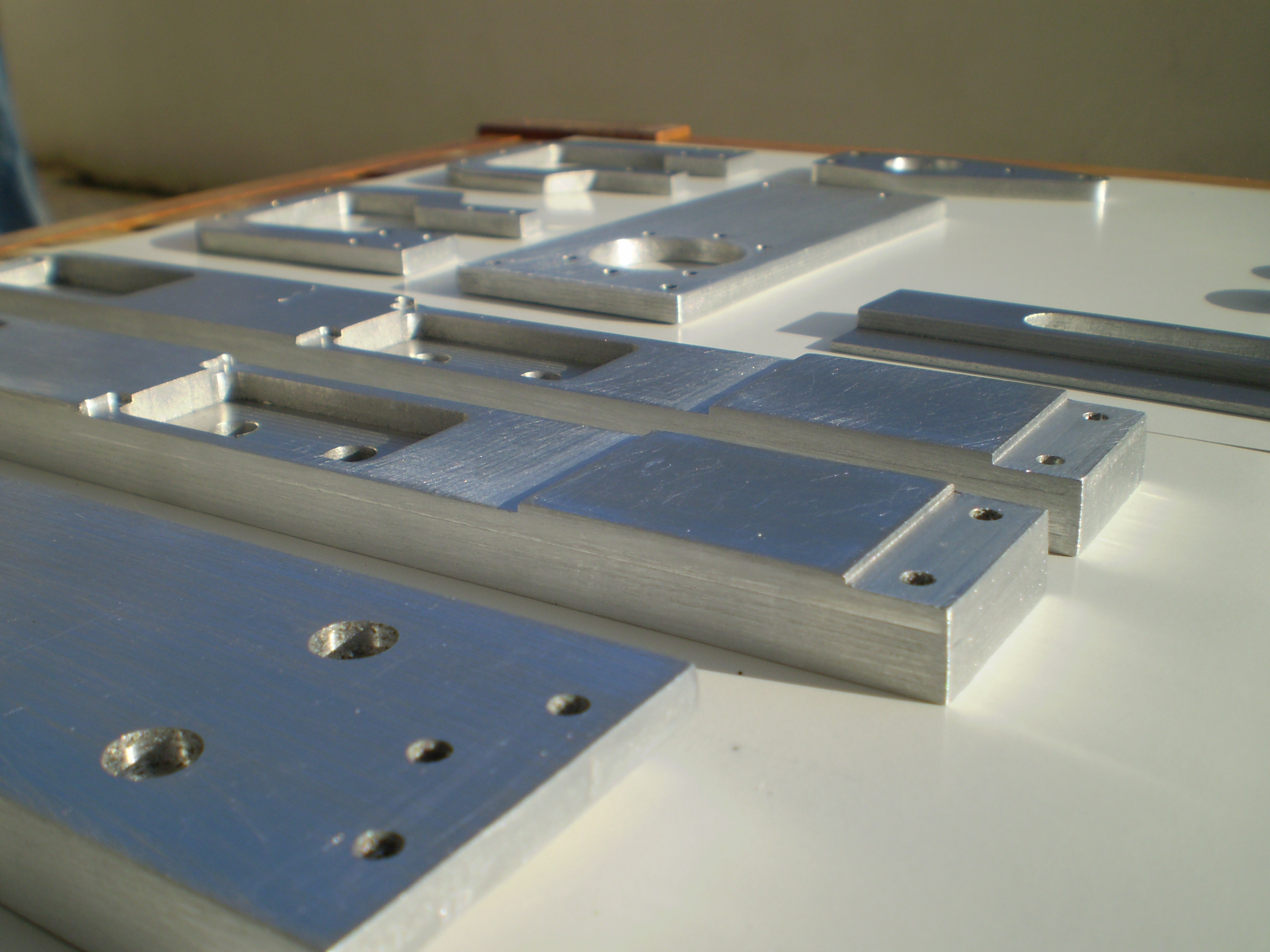
These drawings were then combined and laid down for cutting and machining from stock aluminum bars.
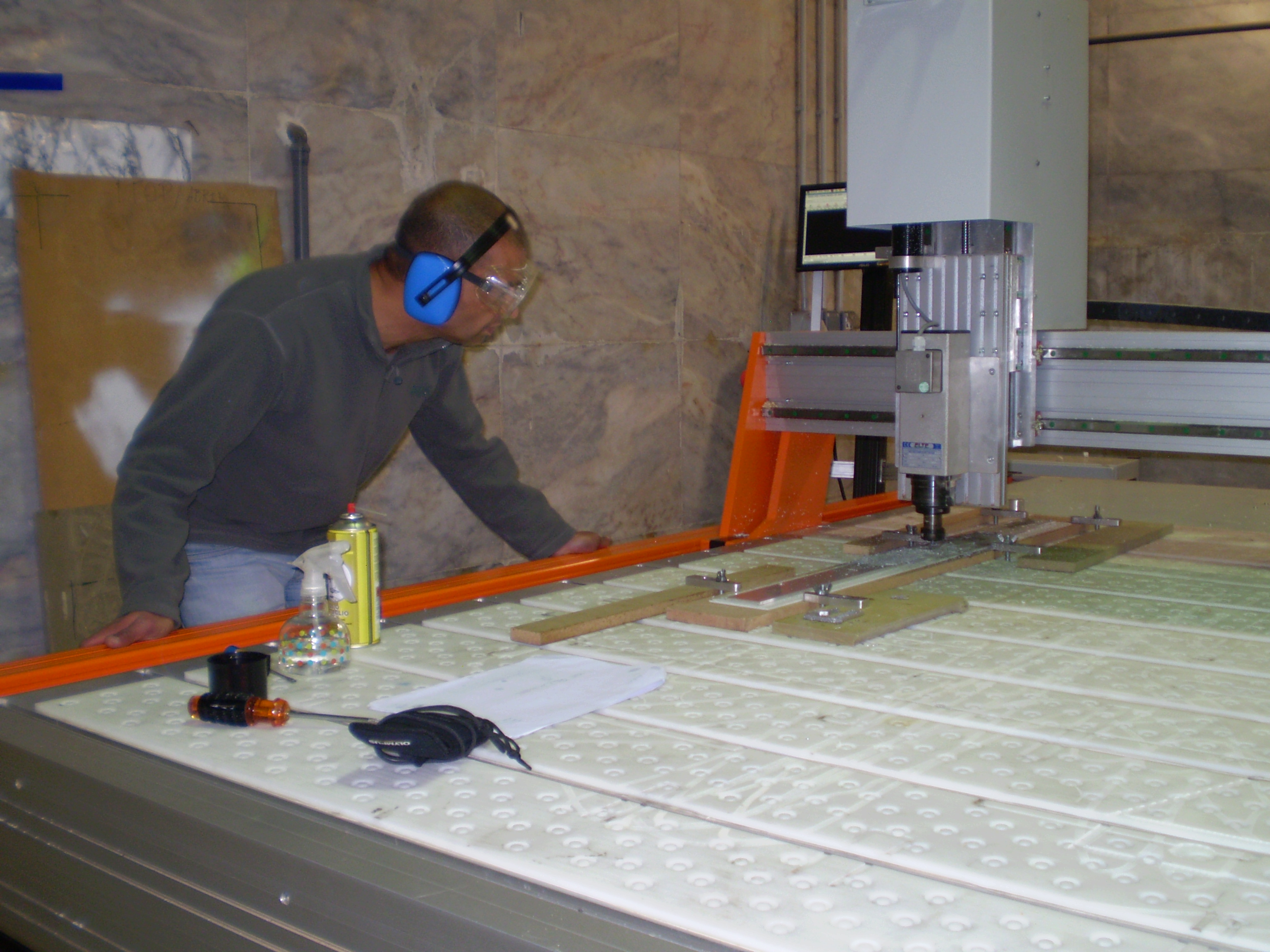
The parts were machined from 6060 aluminum bars with the help and resources of fablab Lisboa, in particular using their Ouplan milling machine.

First attempts at cutting aluminum were disastrous!
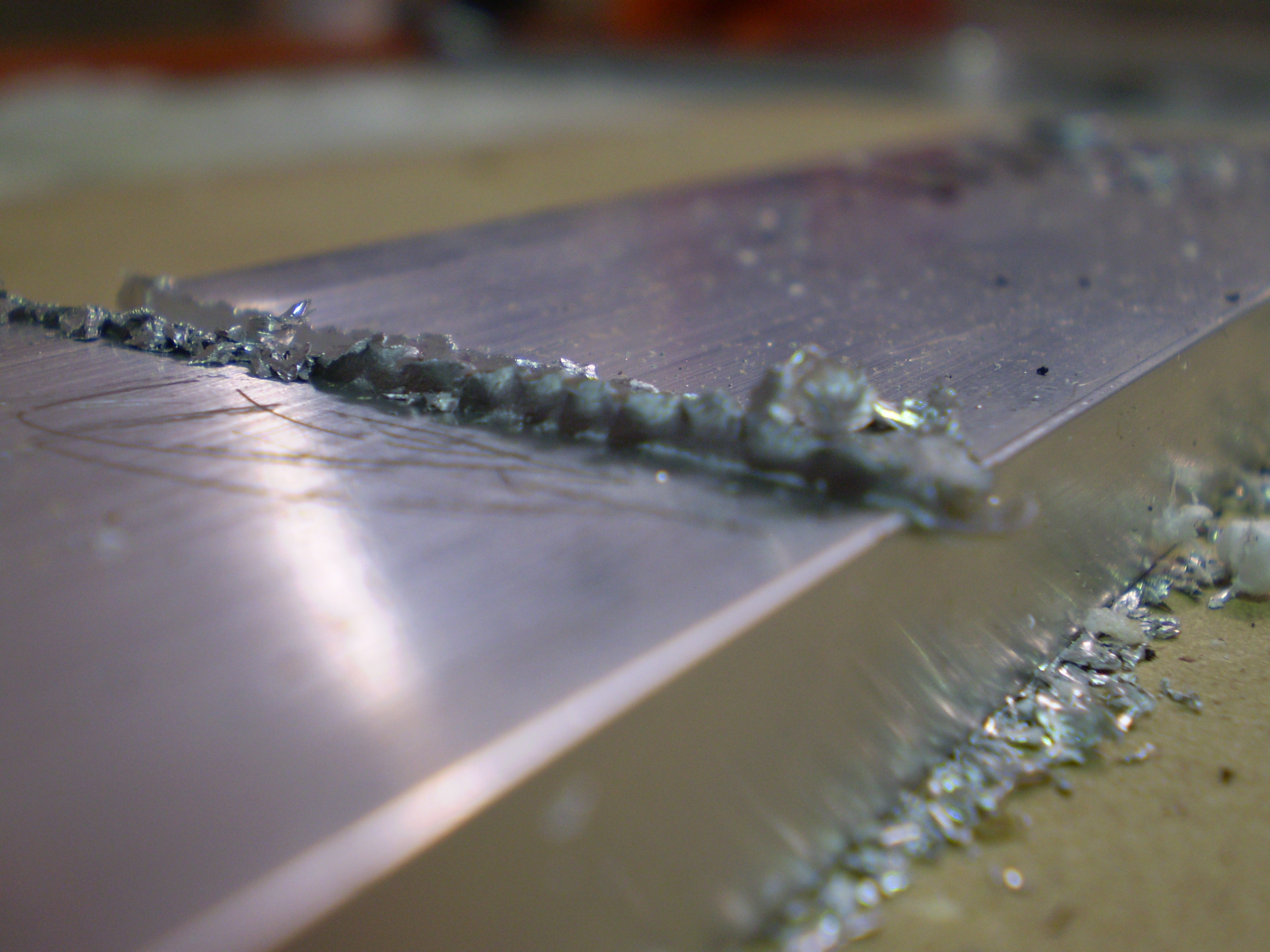
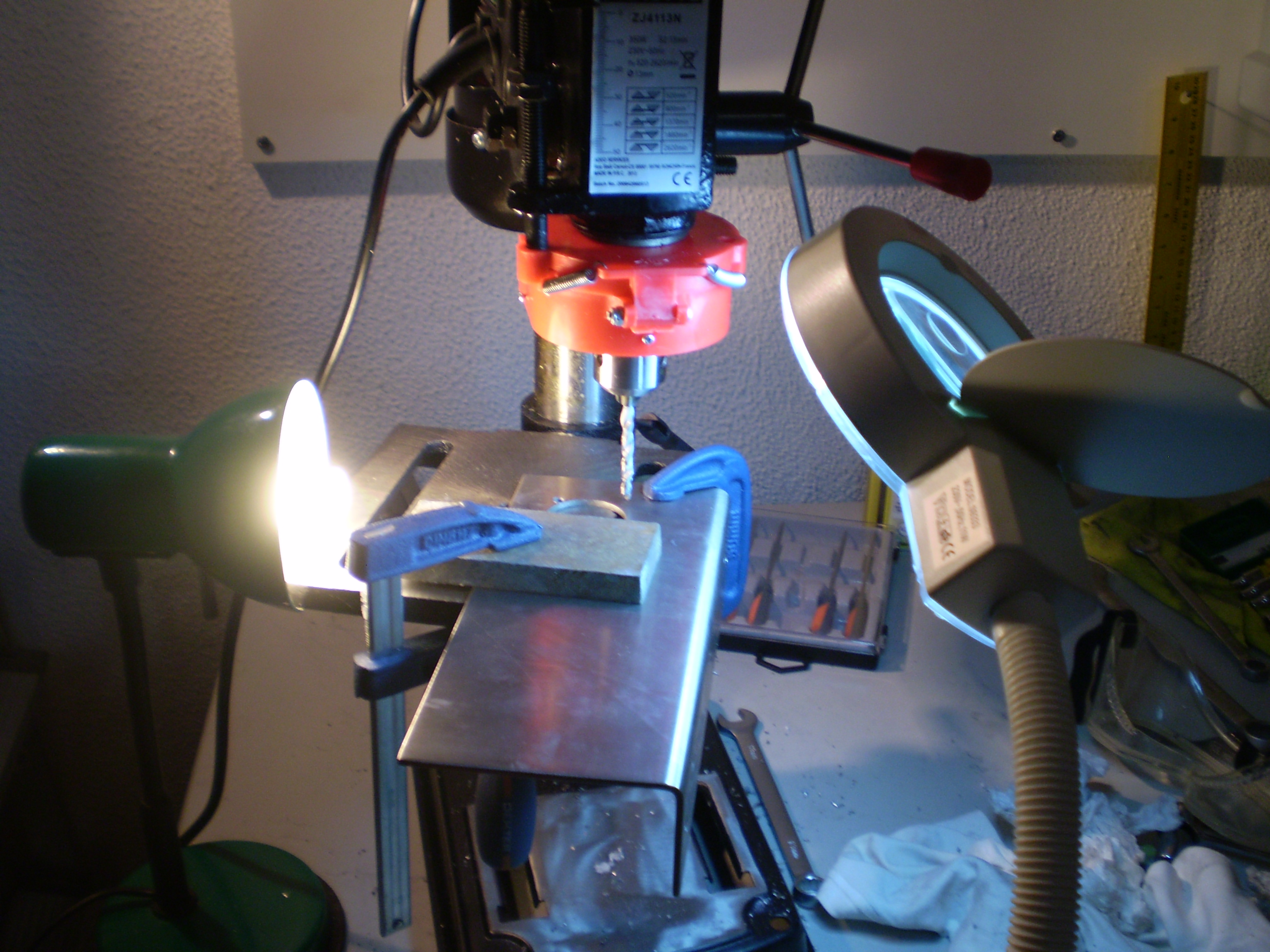
After some tests we settled on conservative settings and HSS/CO 3mm cylindrical end mills:
- Spindle: 5500 rpm
- Feed rate: 5mm/s
- Stepover: 1.2mm
- Stepdown: 0.75mm
A sequence of machining sessions followed – totaling around 20 hours – during which the majority of aluminum parts were cut.
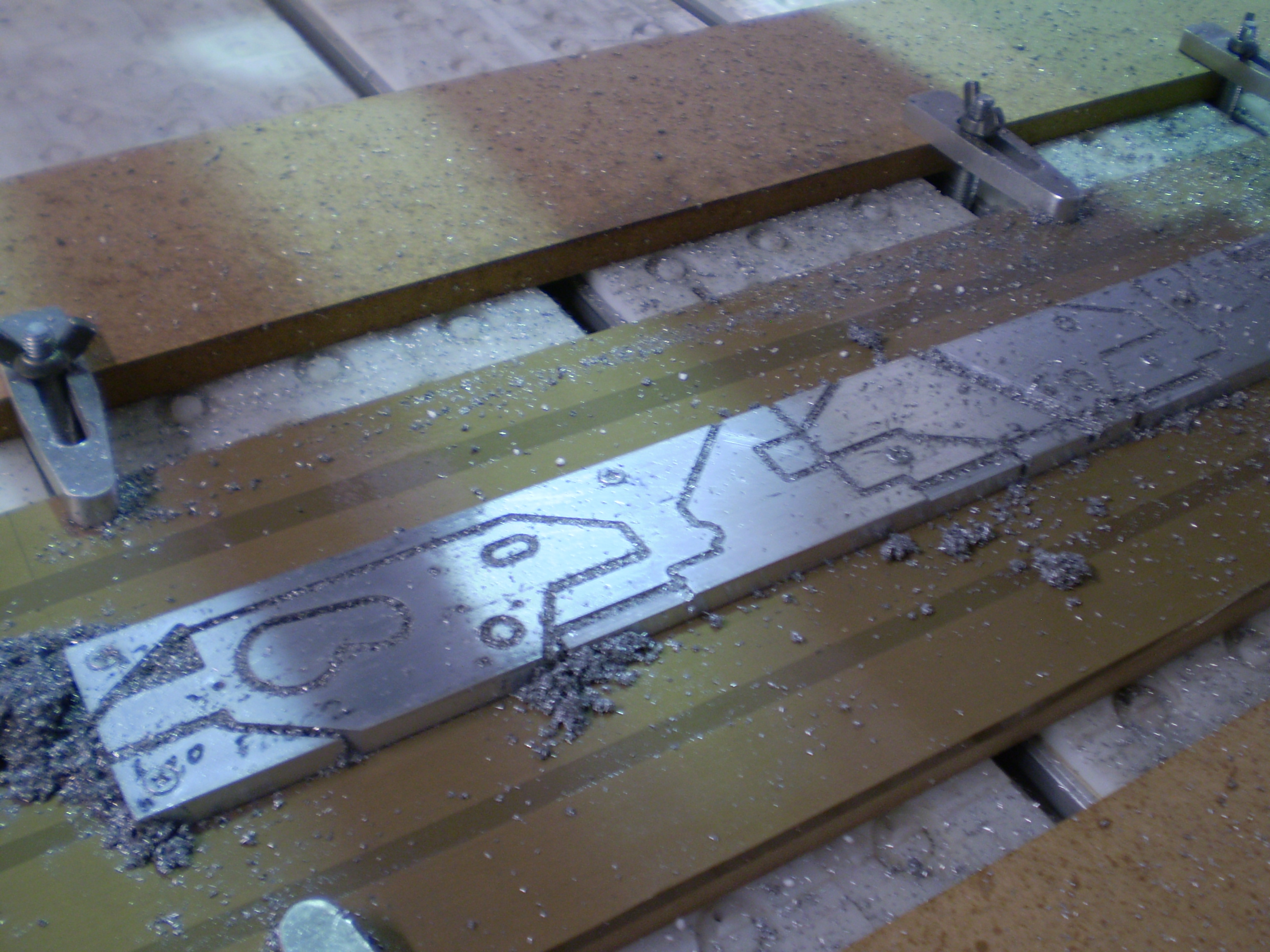
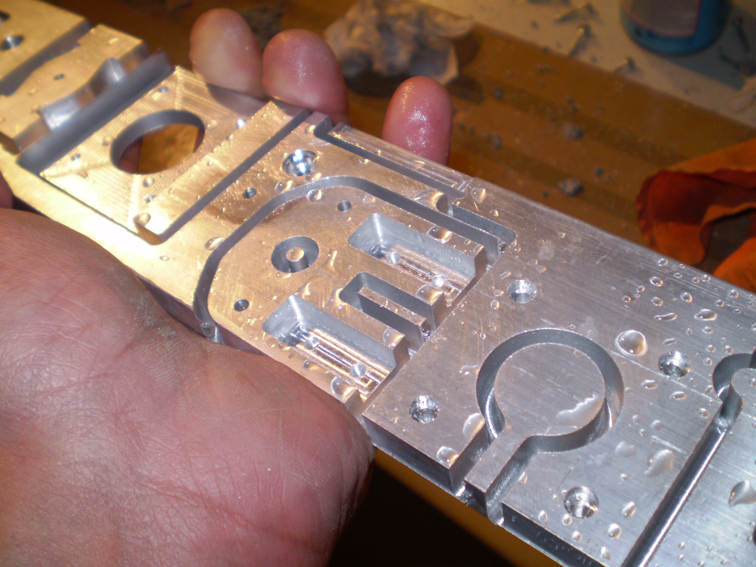
We tried to keep the maximum possible dimensional accuracy with the tools at our disposal. This meant that sometimes we would be positioning a part for over 10 minutes only to perform a single drilling operation.
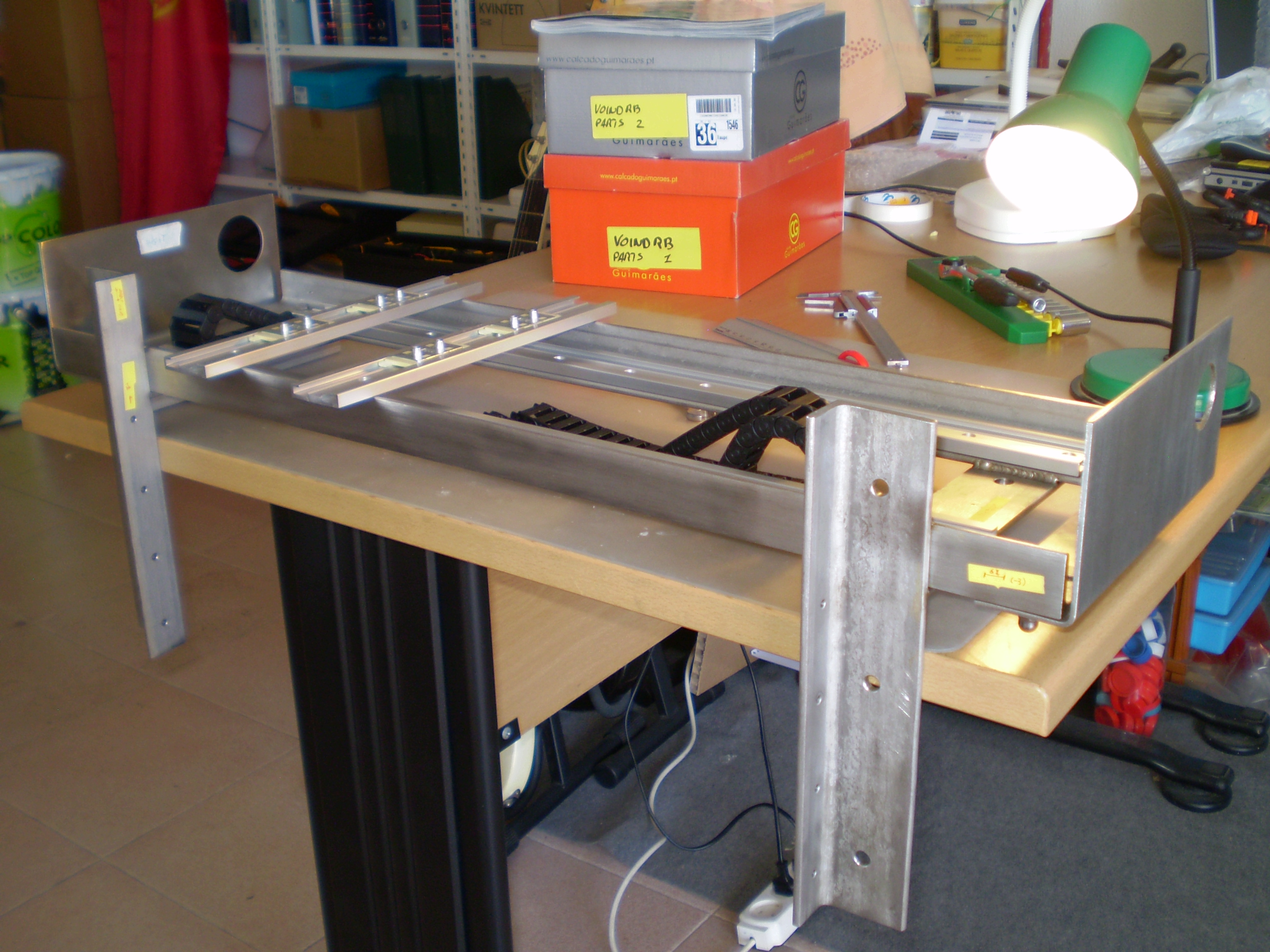
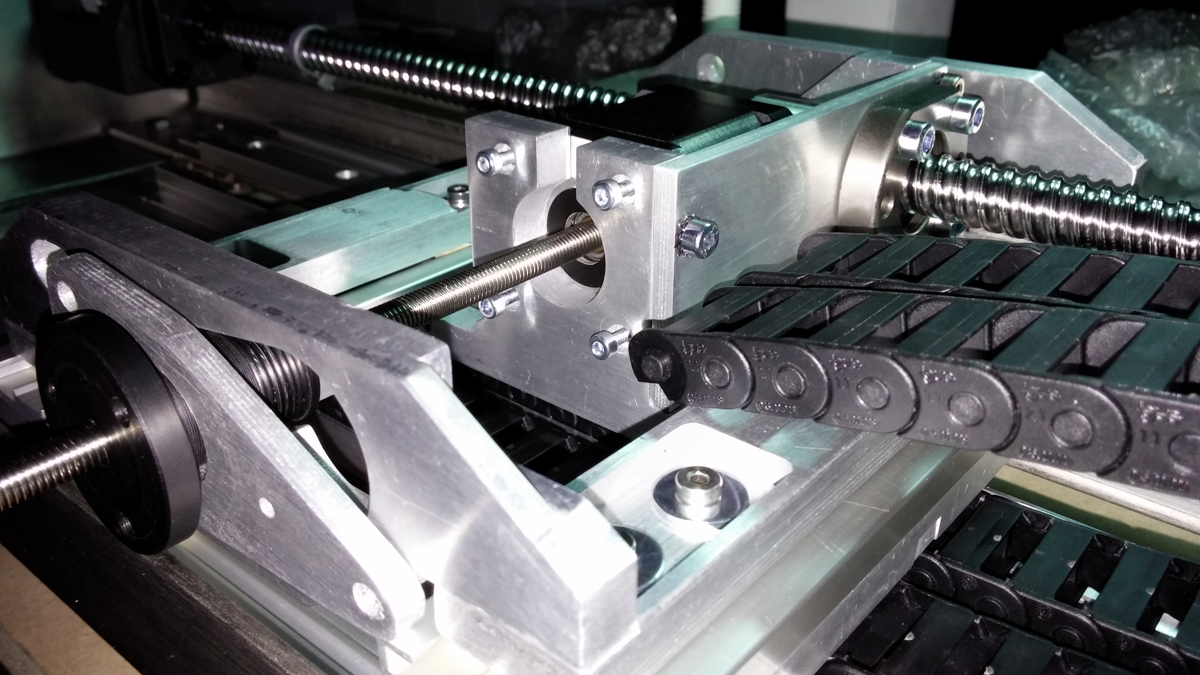
As soon as the first aluminum parts were fabricated we proceeded into initial tests of the assembly fits. These tests validated the dimensional correctness of the parts and the overall clearances which were calculated during the early stages of the design.
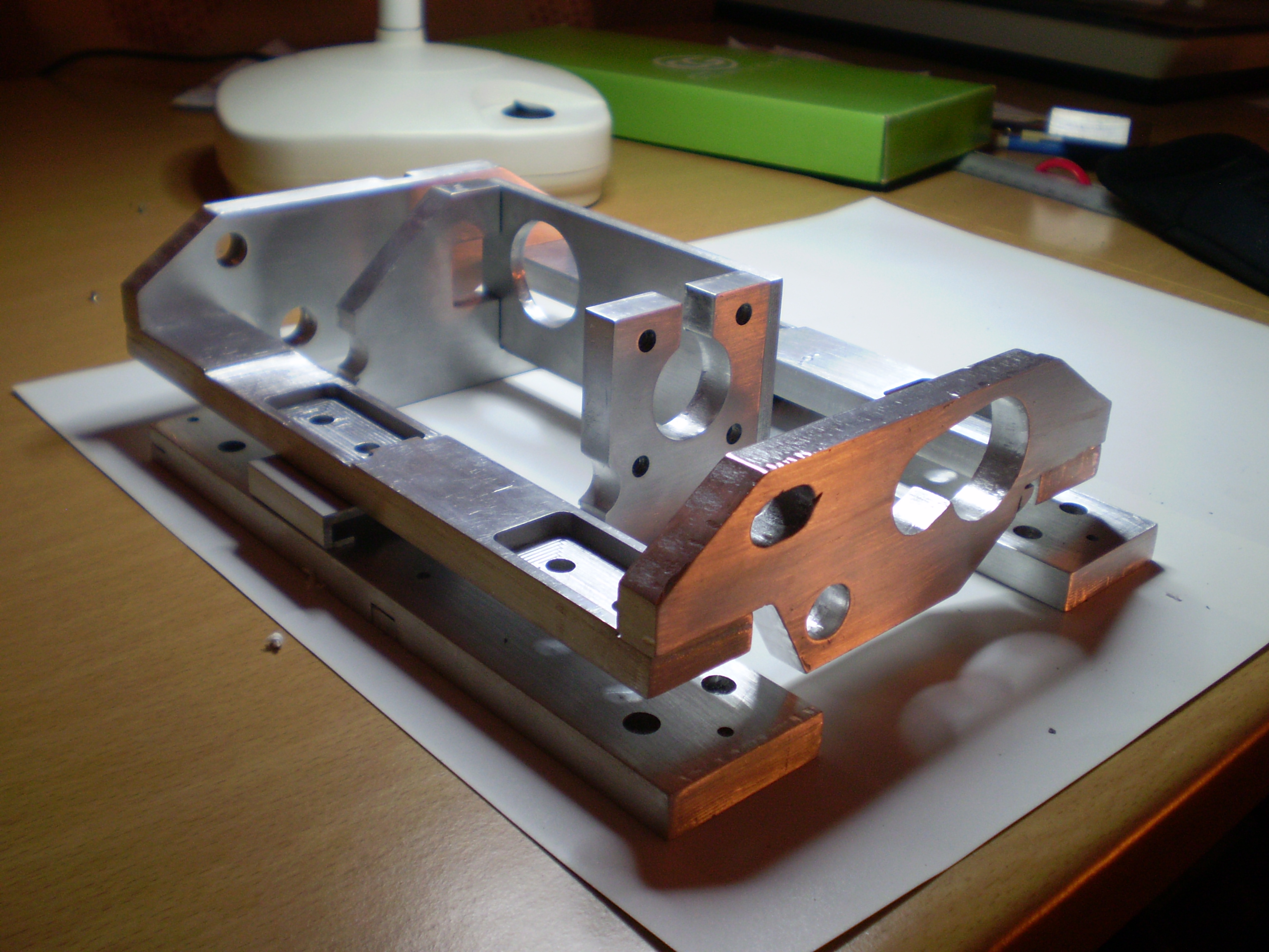
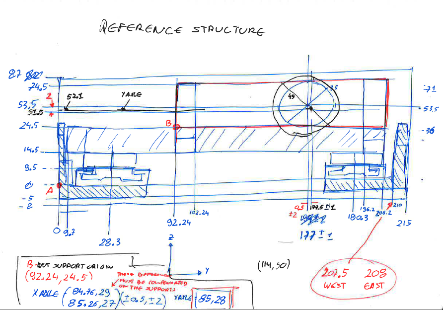
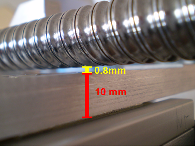
For example the clearance between the ballscrew and the surface of one of the parts is less than one millimeter across the entire width of the robot. This is one of several design decisions which allowed us to cram three DOFs (degrees of freedom) with motors and associated mechanics within a 9 cm height footprint.
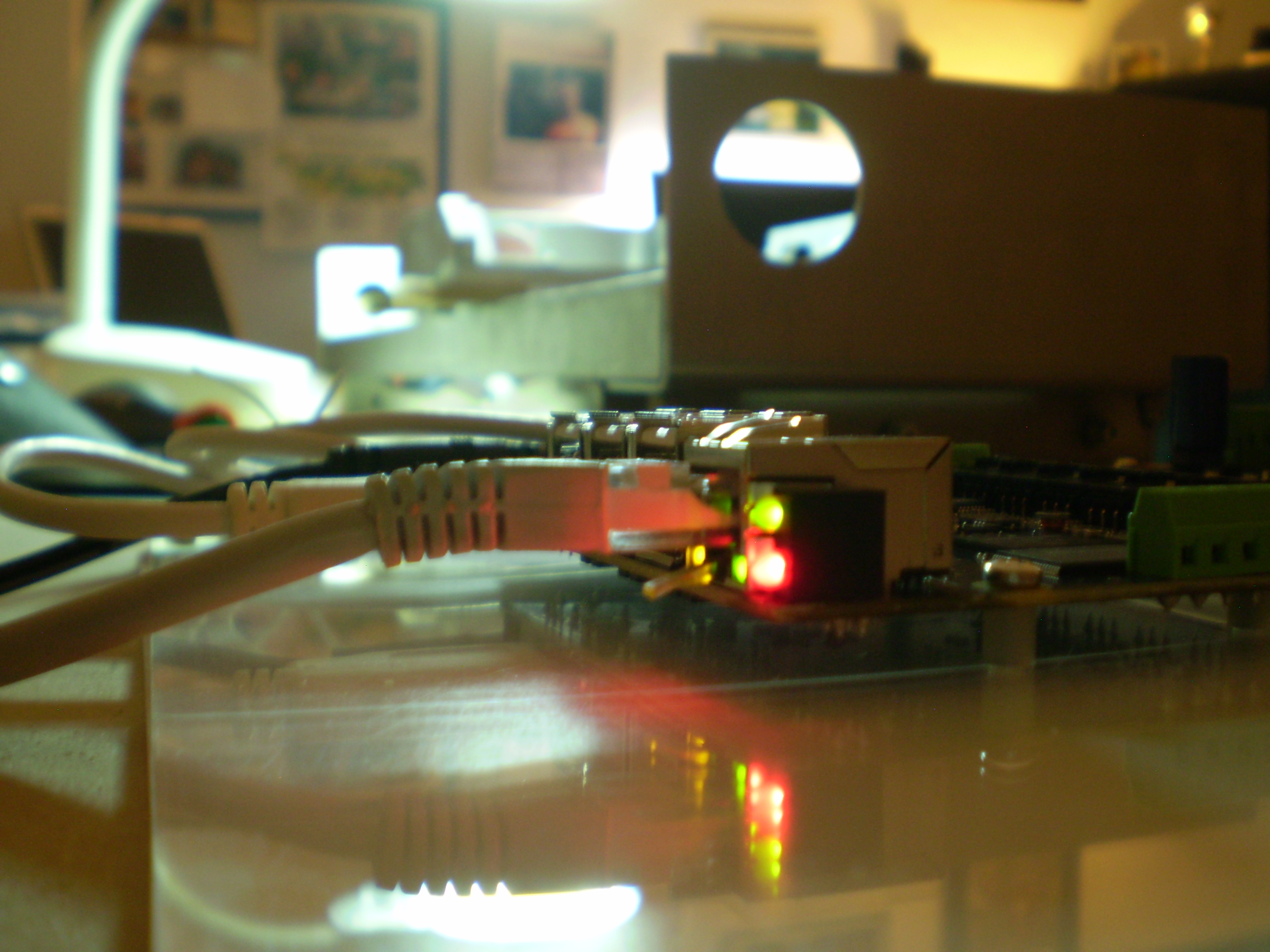
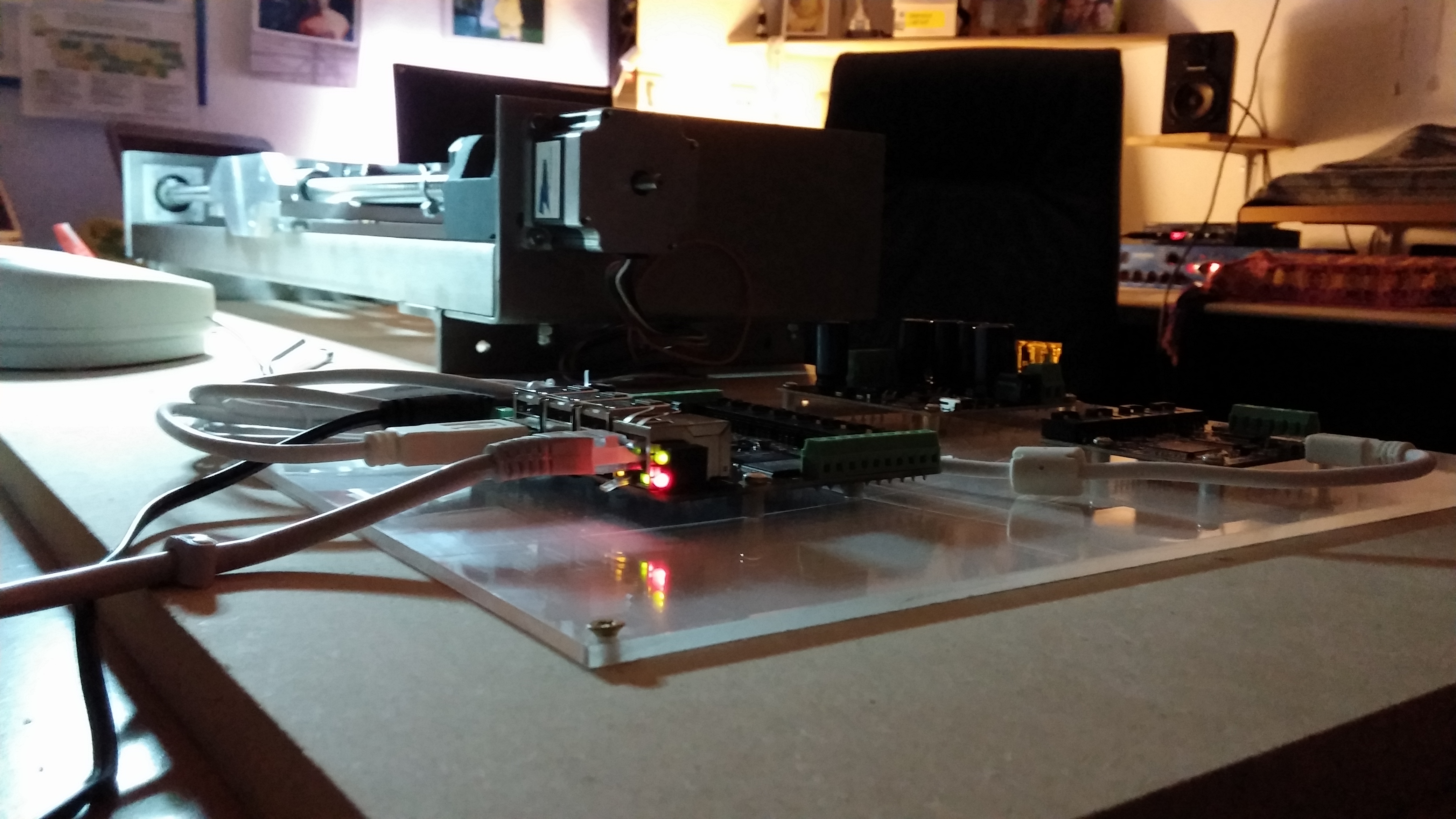
The control electronics is being built and tested side-by-side with the mechanical components. In due time it will be attached to the robot chassis but until then it is laid out on an area of the assembly zone protected by a plastic transparent cover.