Strong-arm tactics

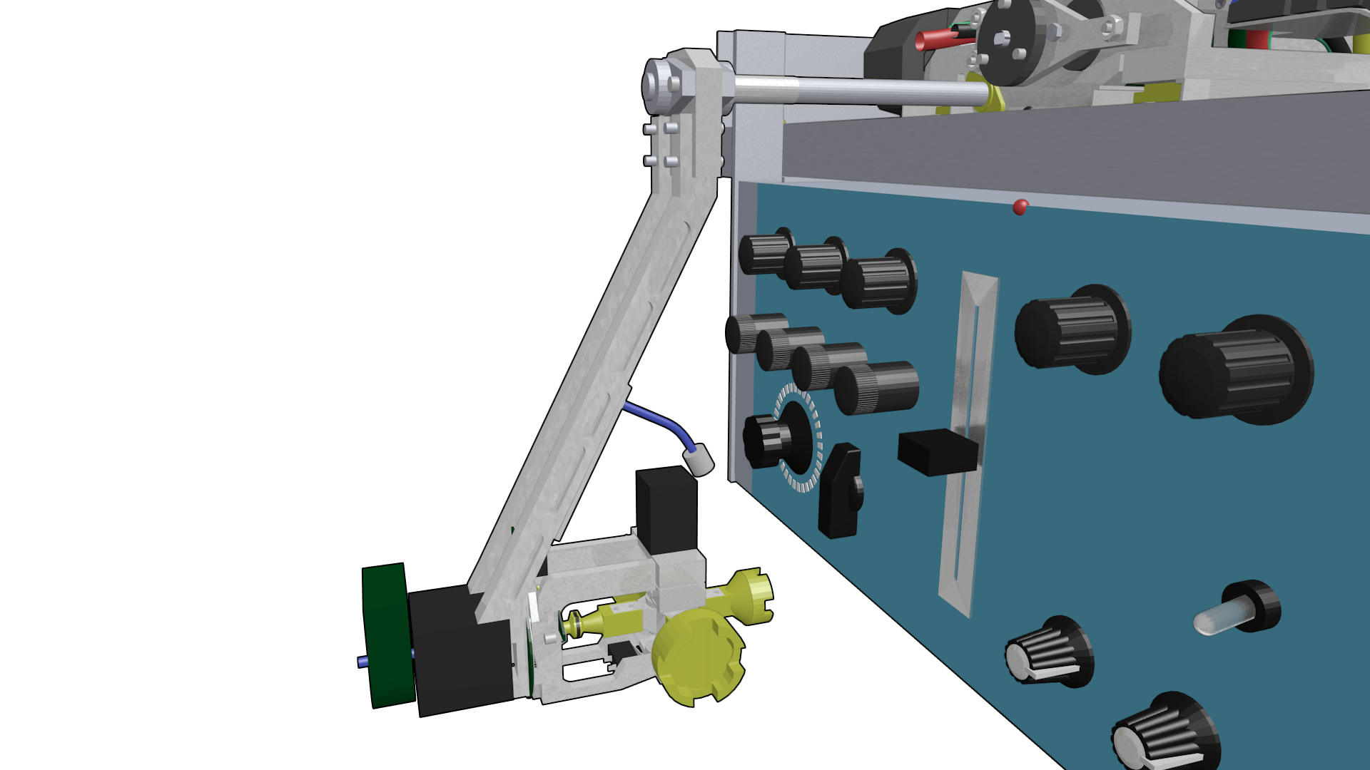
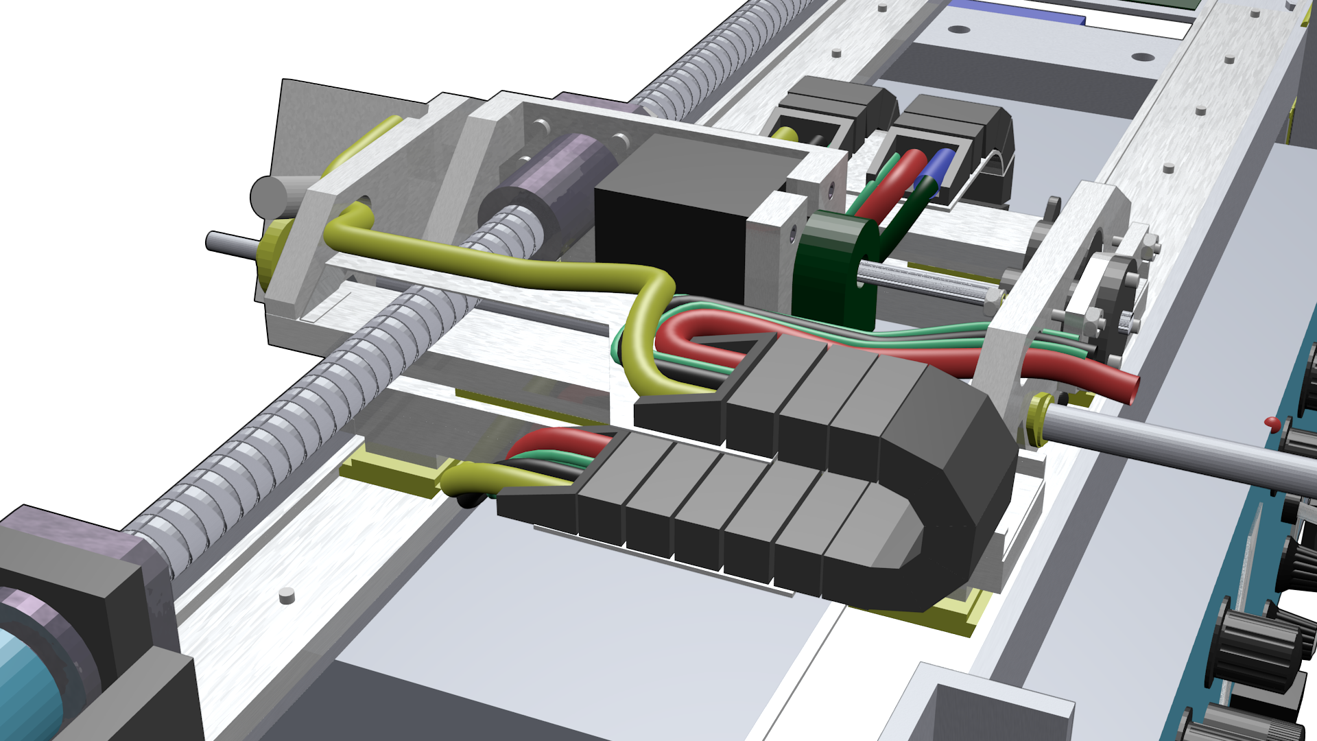
The whole purpose in life for the voind robot is to actuate the physical controls of vintage studio equipment, effectively allowing the remote operation of the equipment.

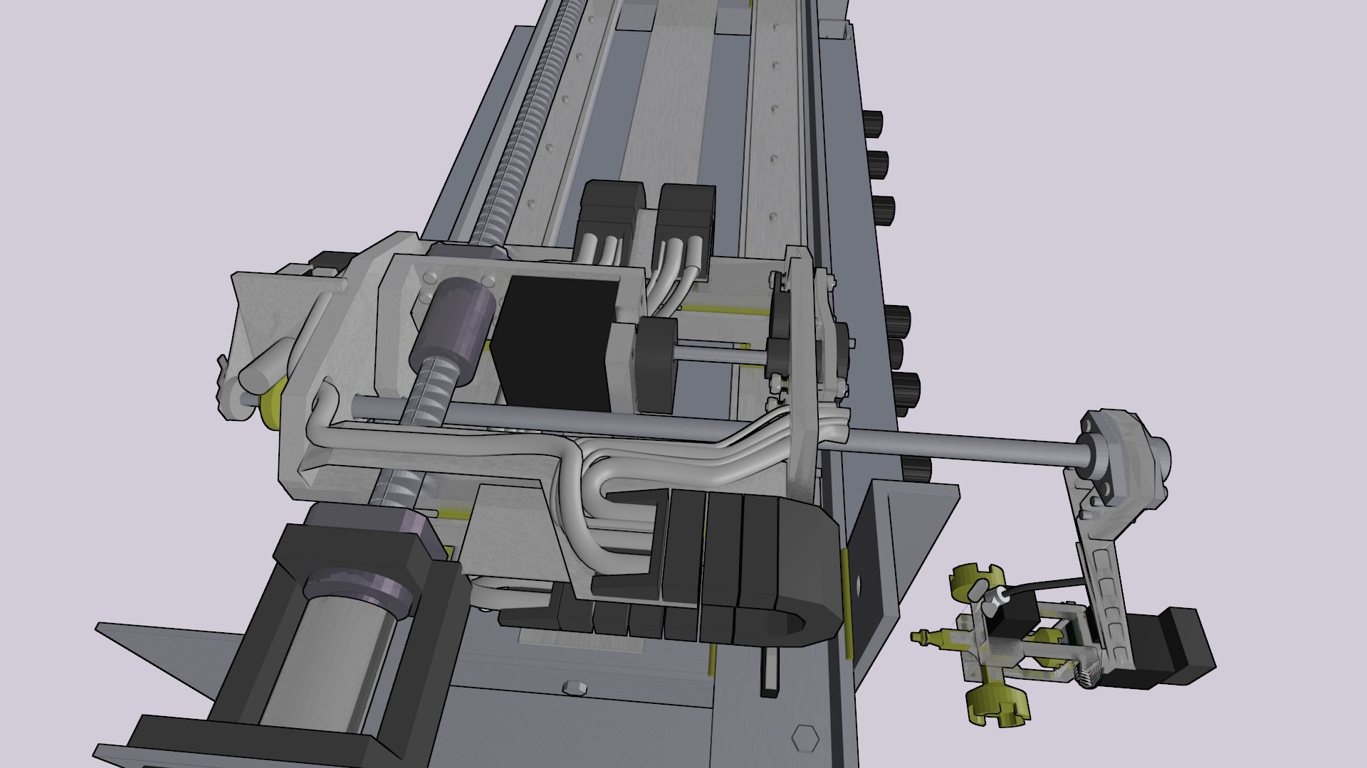
To accomplish this the end effector must be quickly and precisely positioned over the controls and for that a strong arm is required.

arm

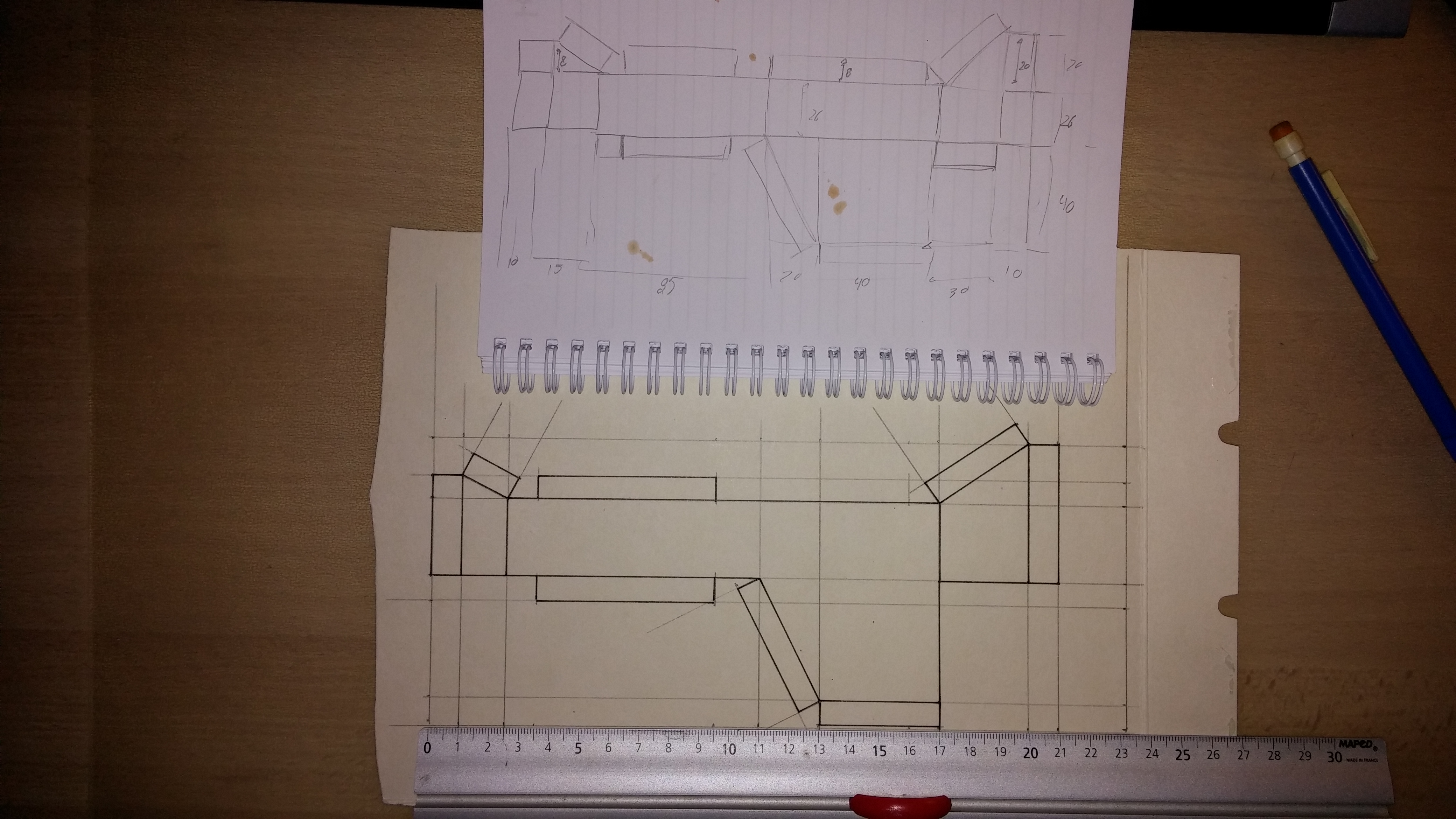
The main requisites for the arm assembly were:

  • the weight (all the assembly should weight less than 750g)
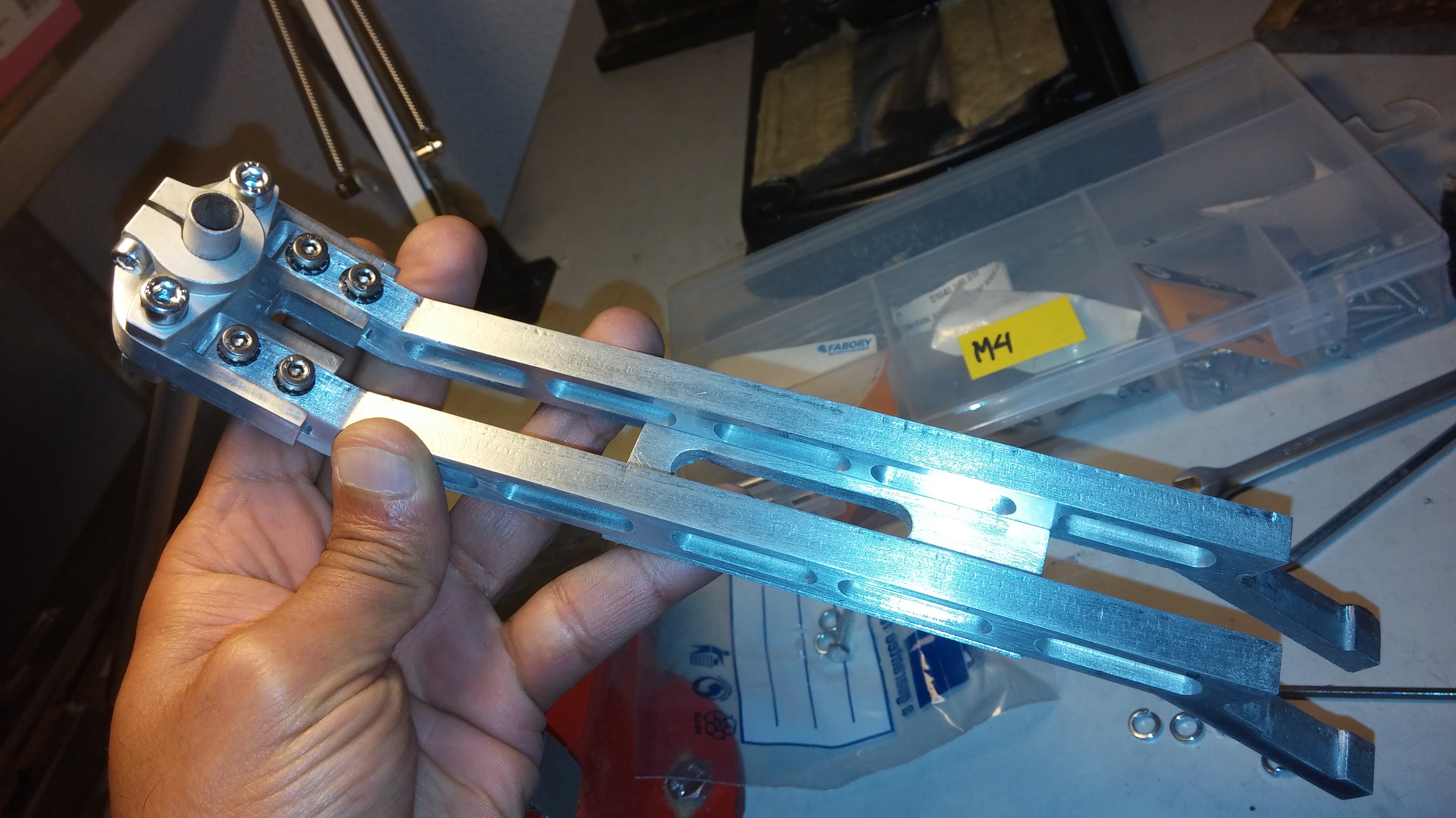
  • the arm’s structural rigidity (resistance to torsion on all axes)
  • the rigidity of its clamping to the shaft

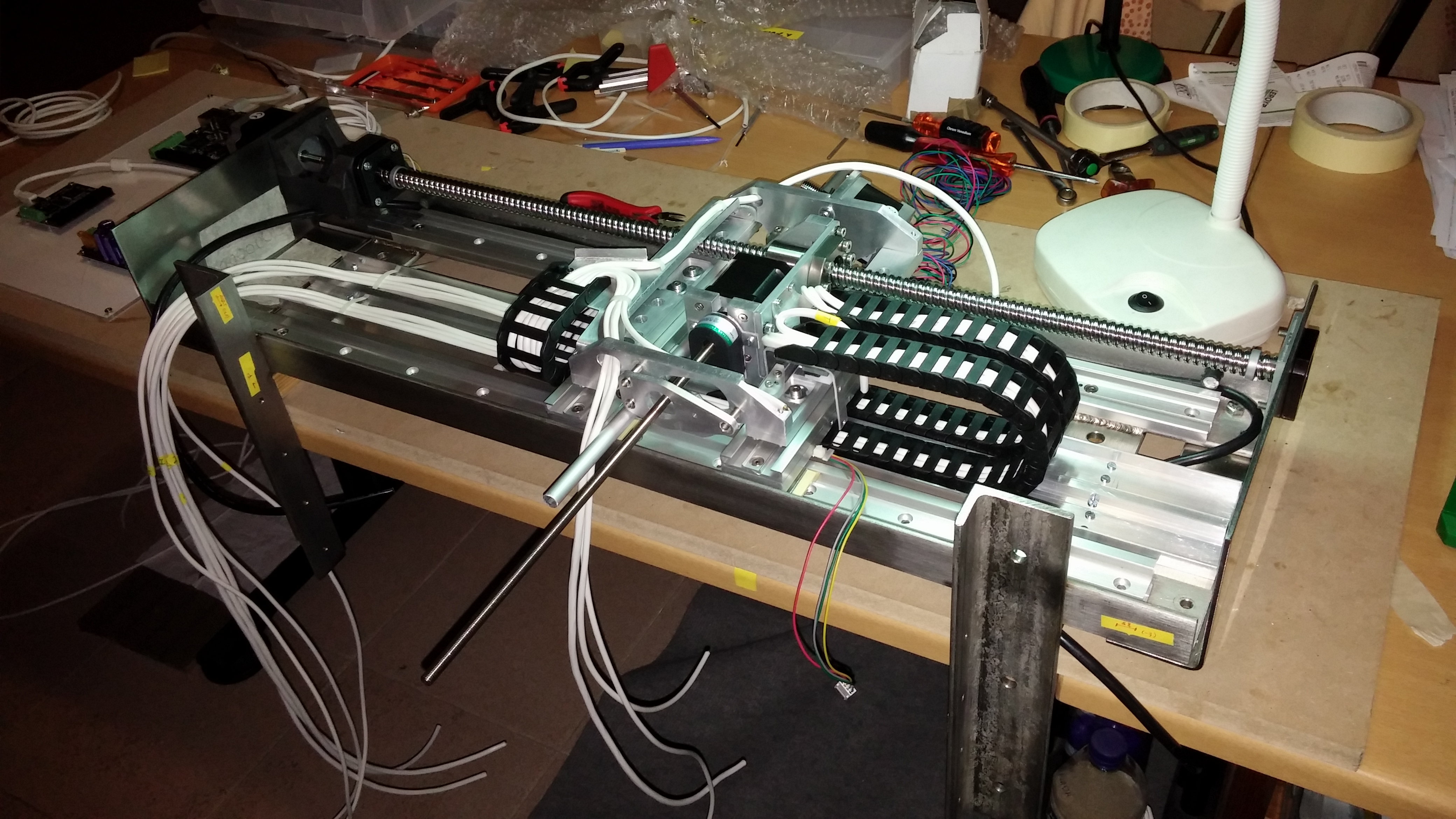
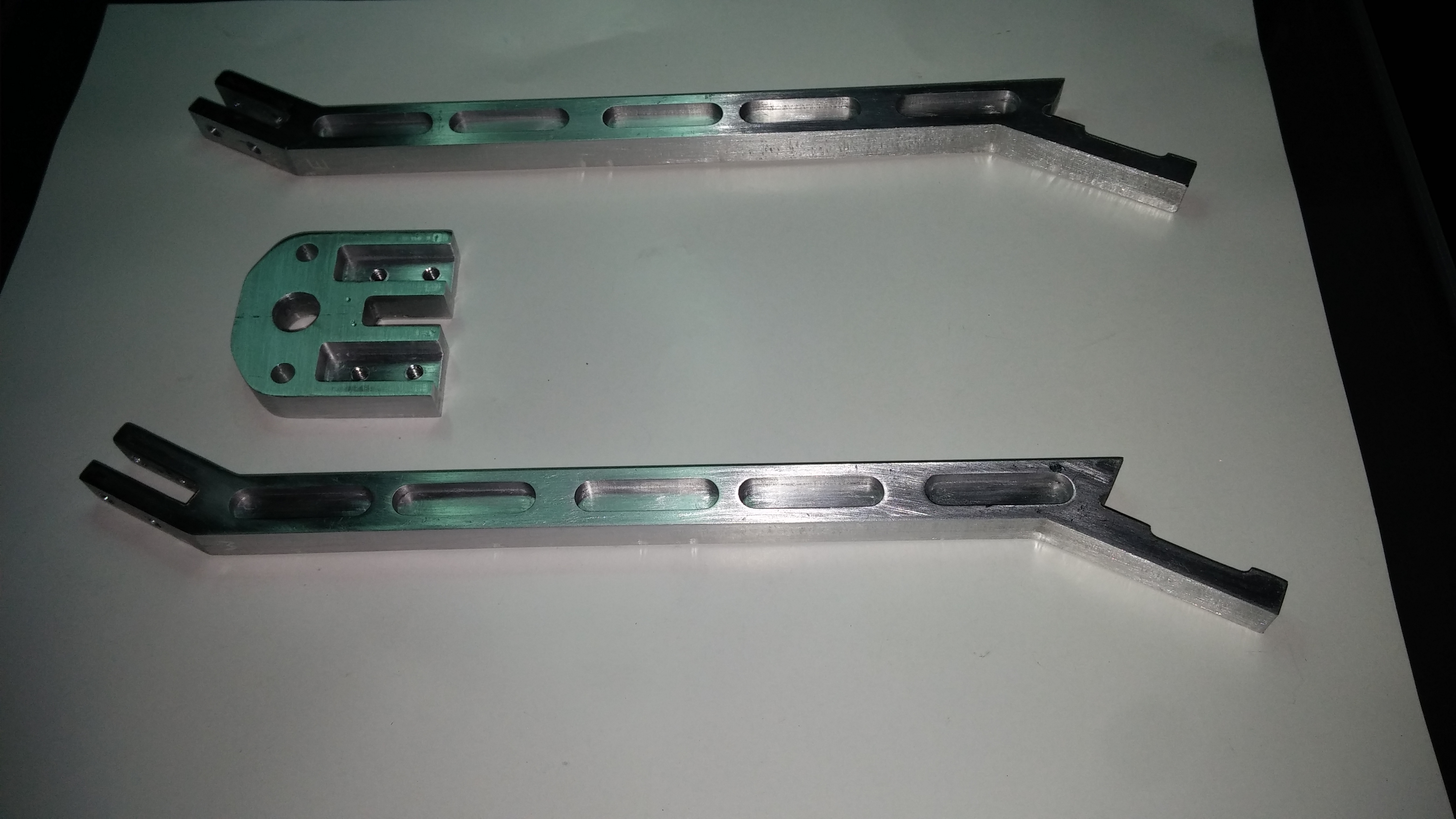
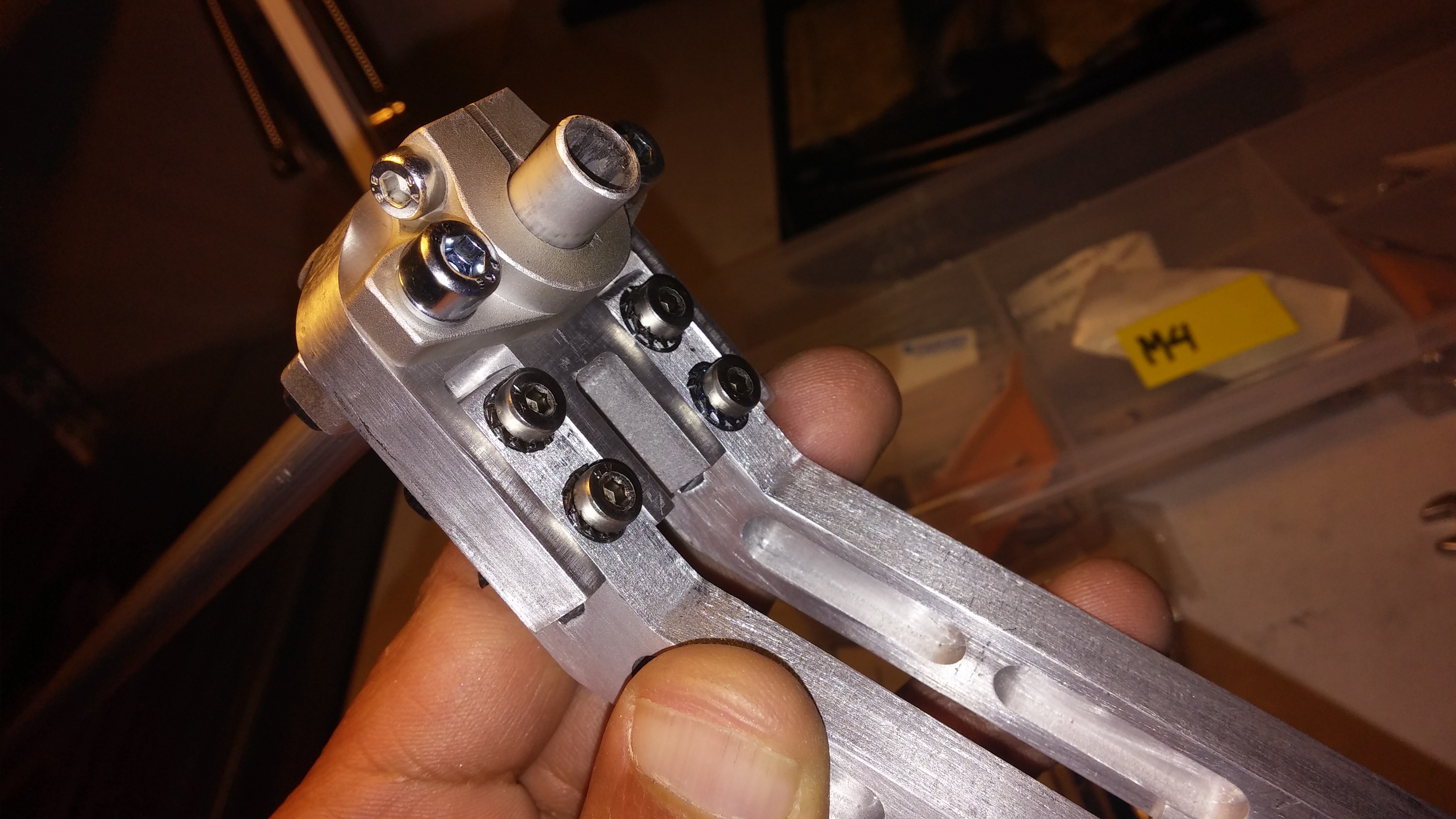
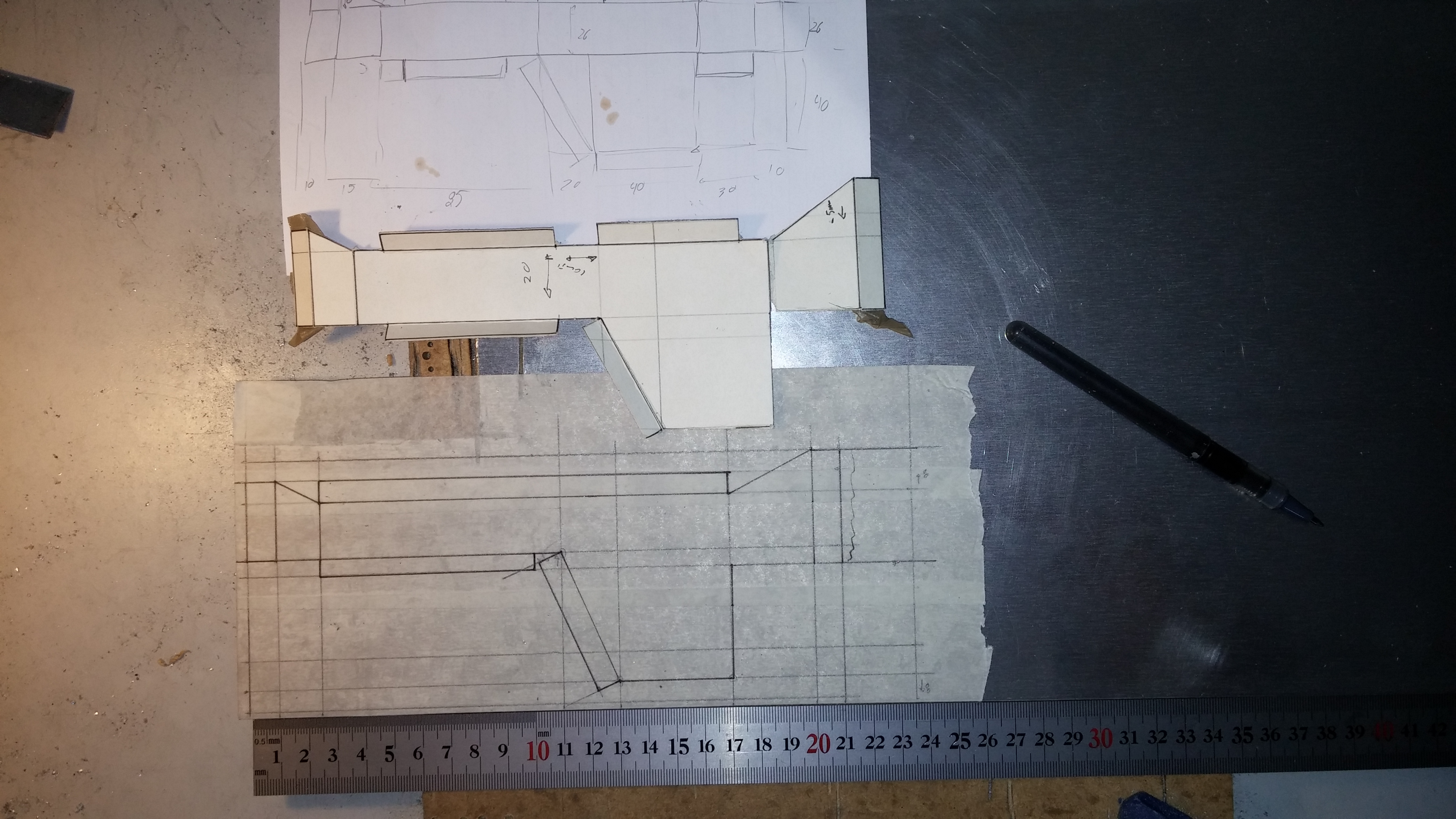
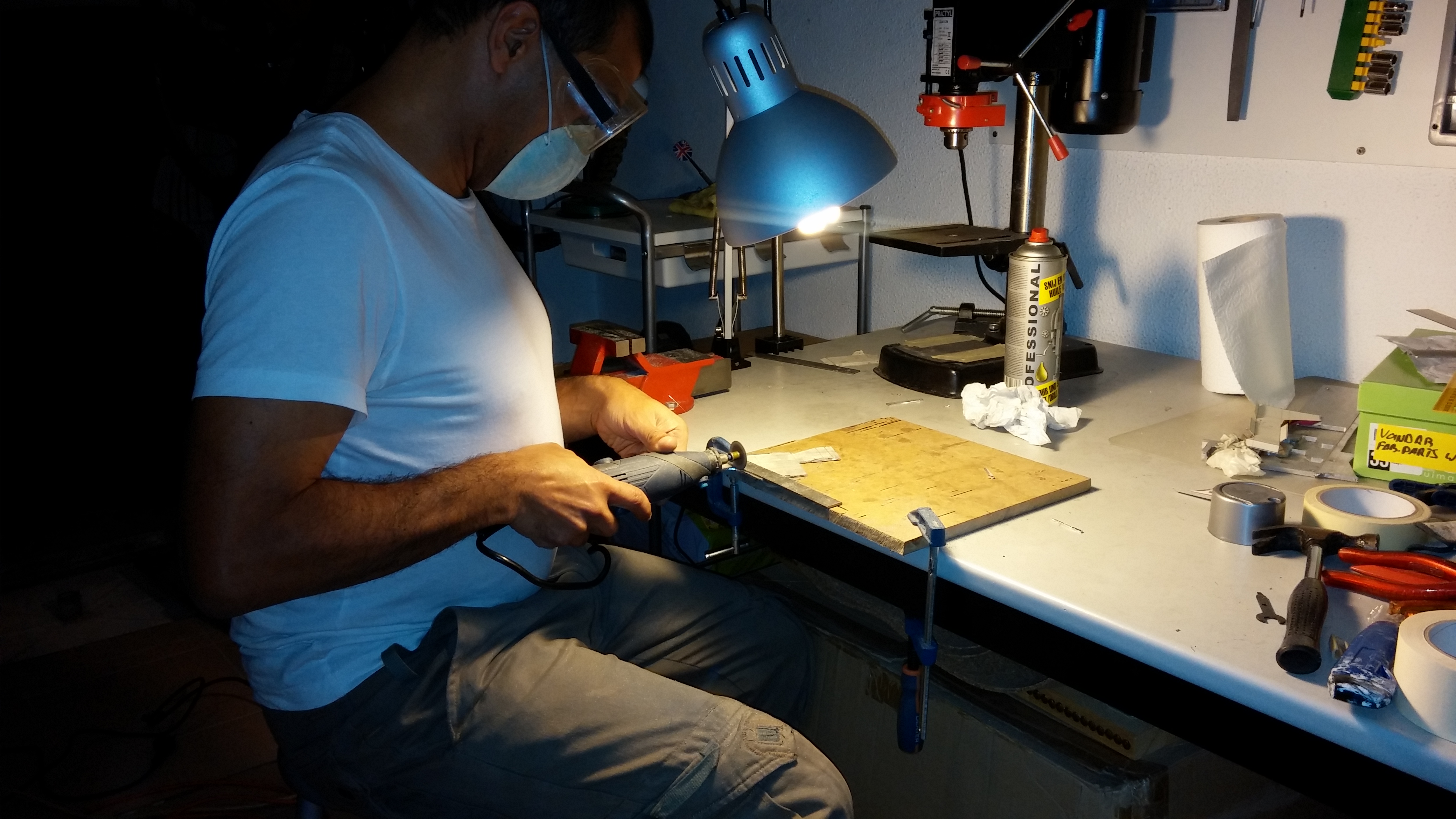
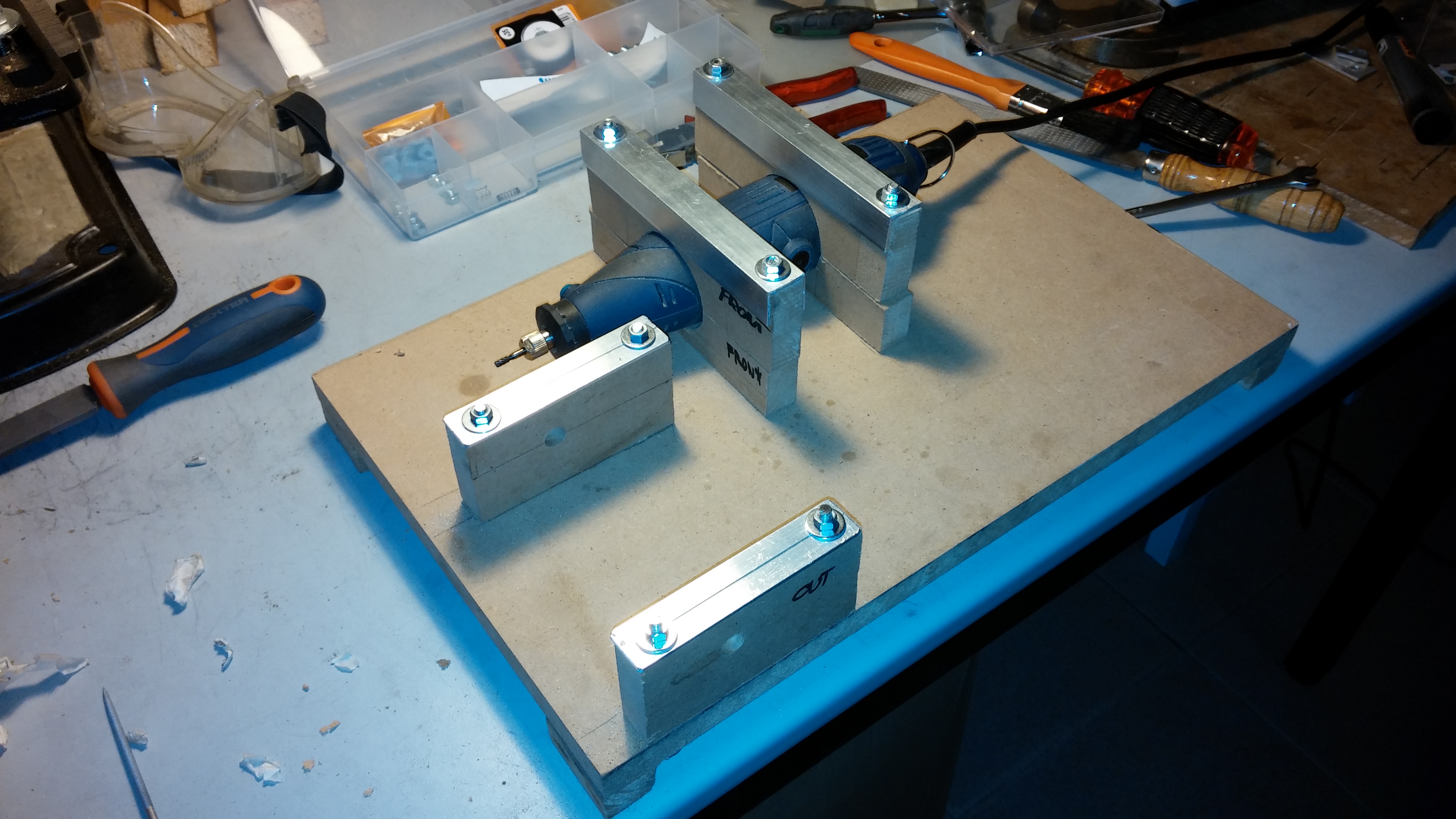
The arm structure is made of aluminum which was first machined using a CNC router.


OLYMPUS DIGITAL CAMERA

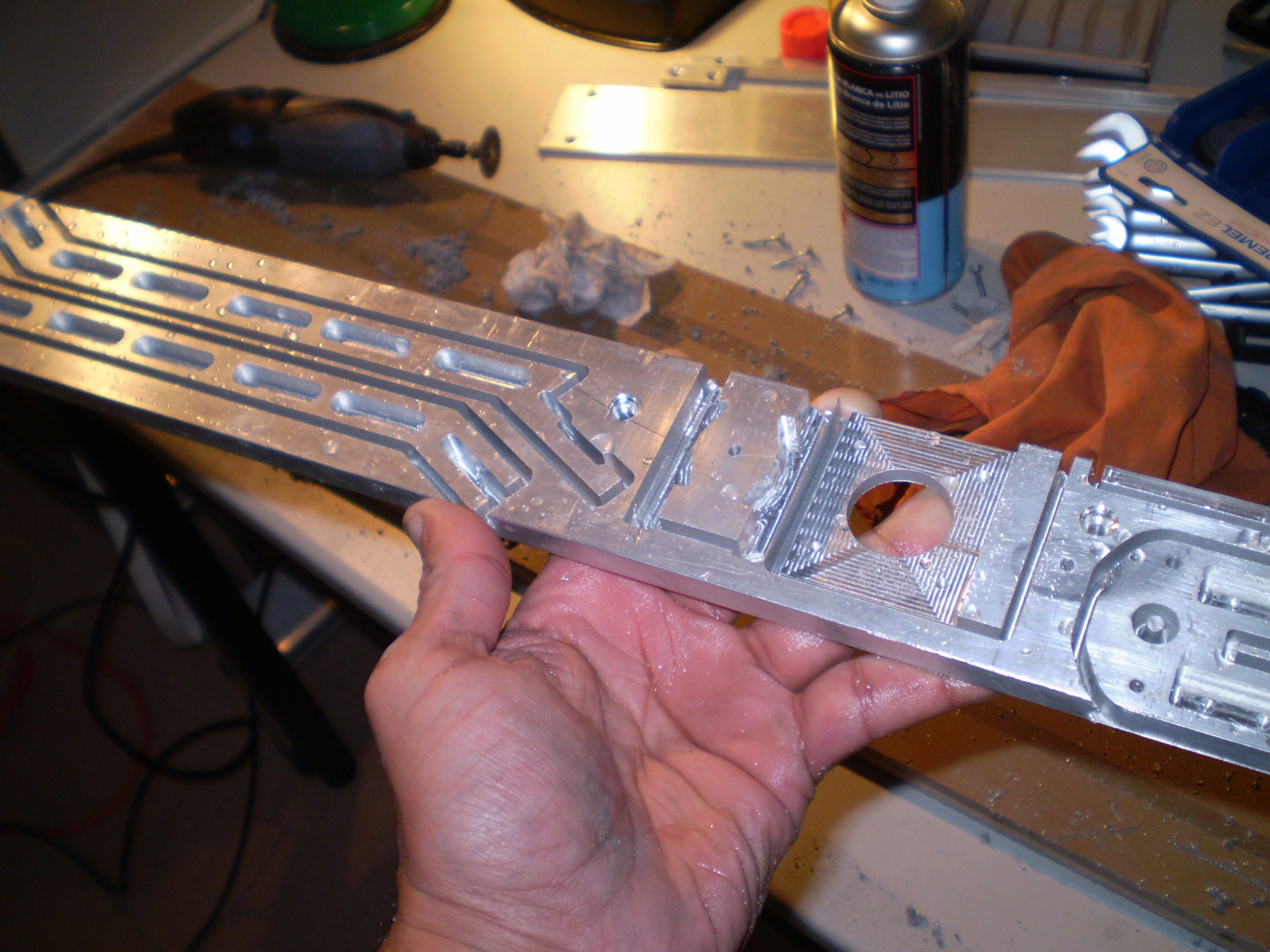
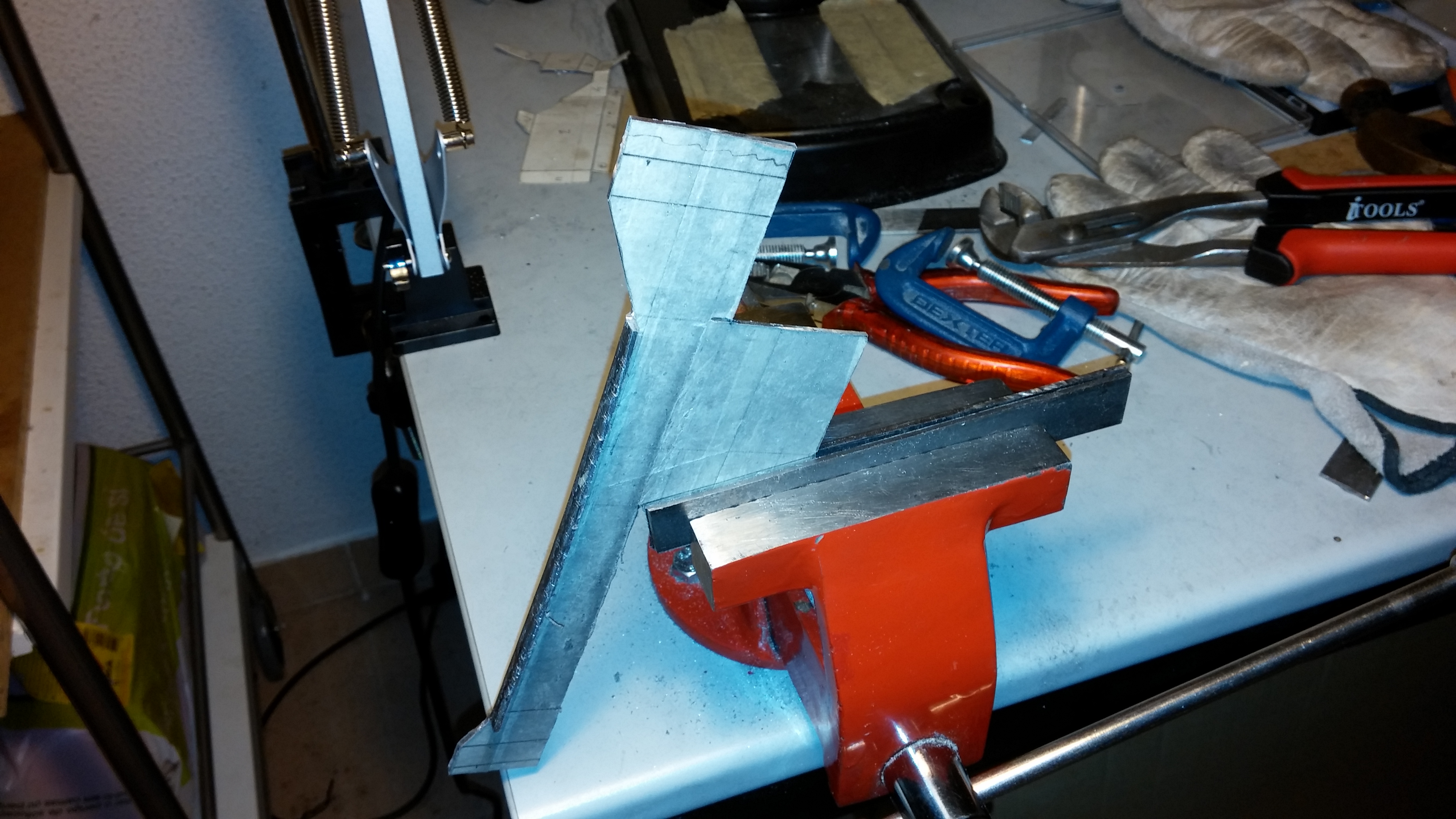
After cleaning up the parts their dimensions were checked and minor adjustments made so they would fit precisely into one another.

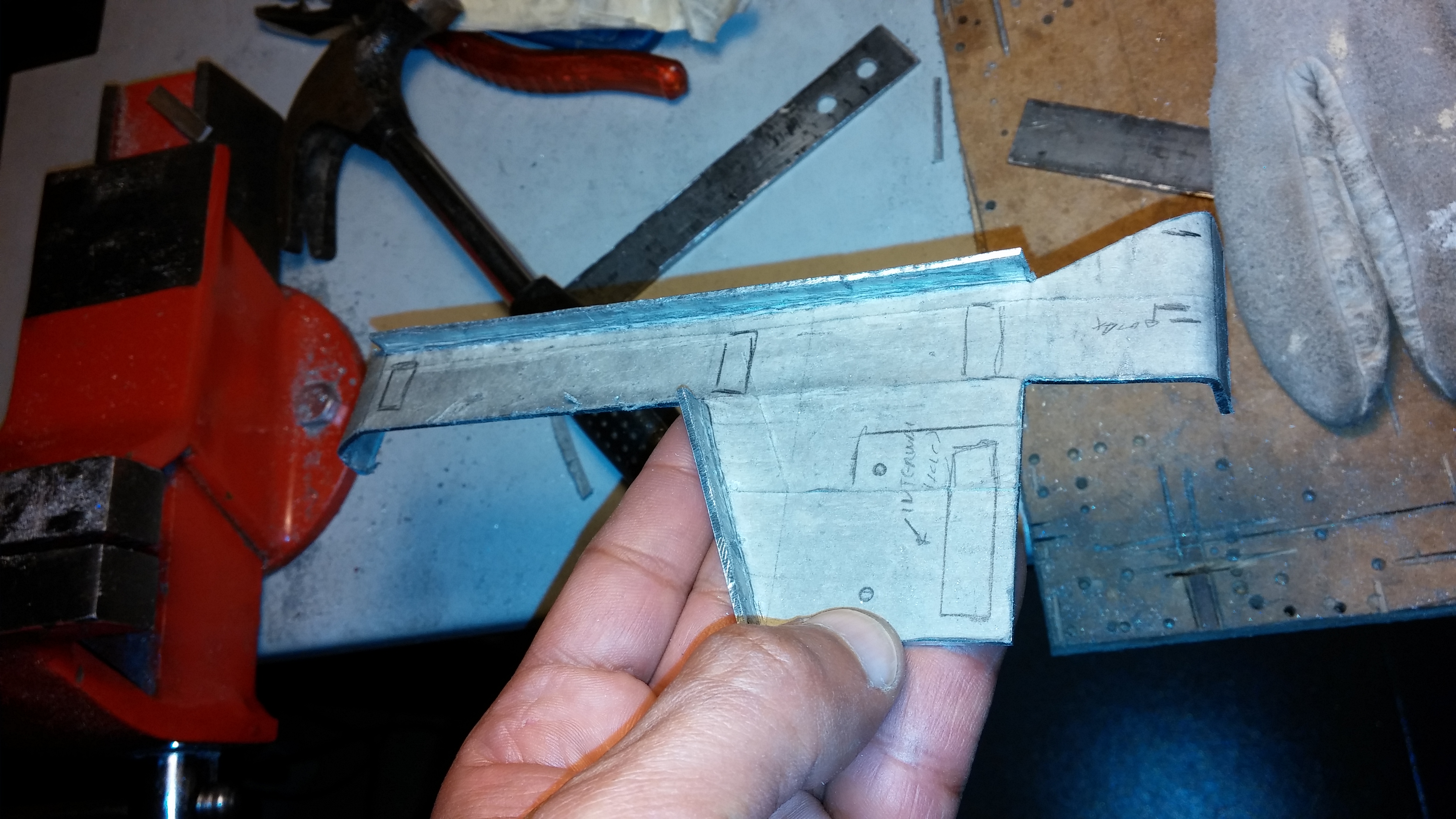
Initial assembly allowed us to mark the exact locations for the fixing screws, which were then carefully drilled through the temporarily joint parts.


CAM00280

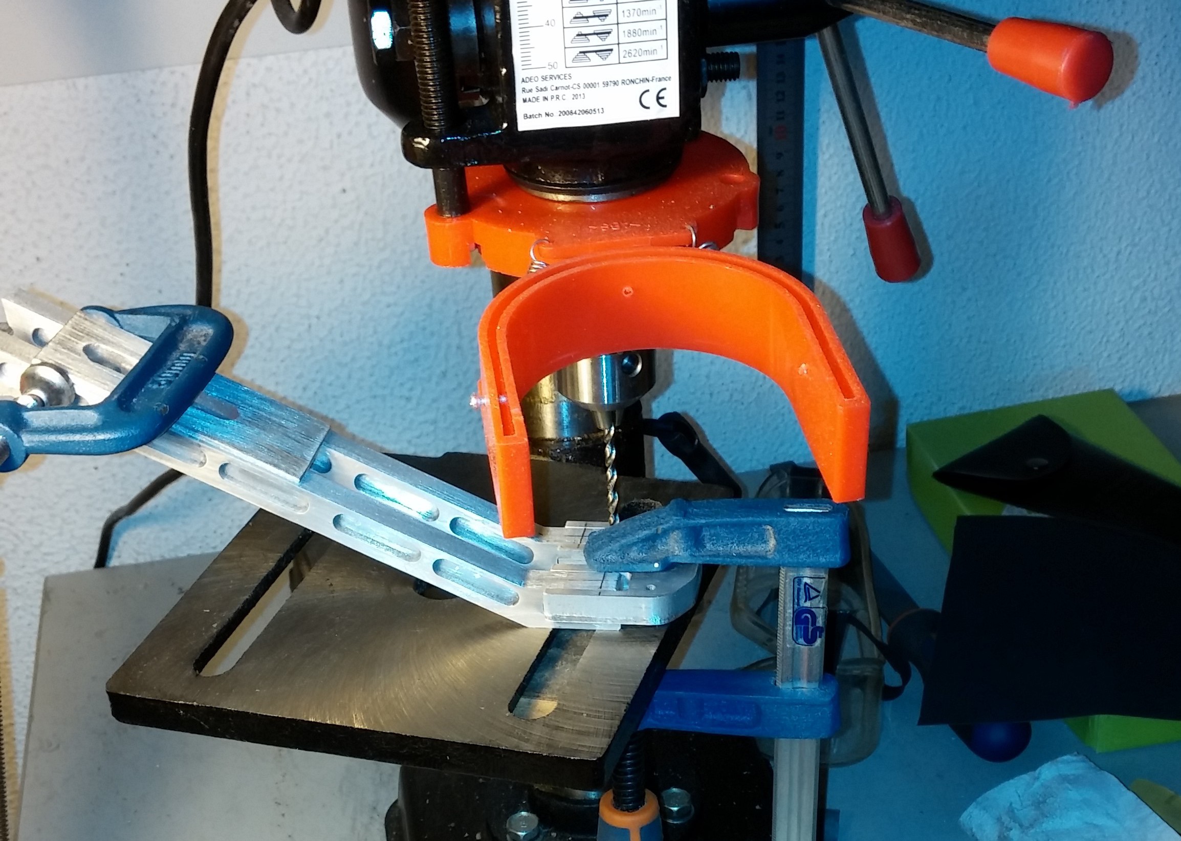
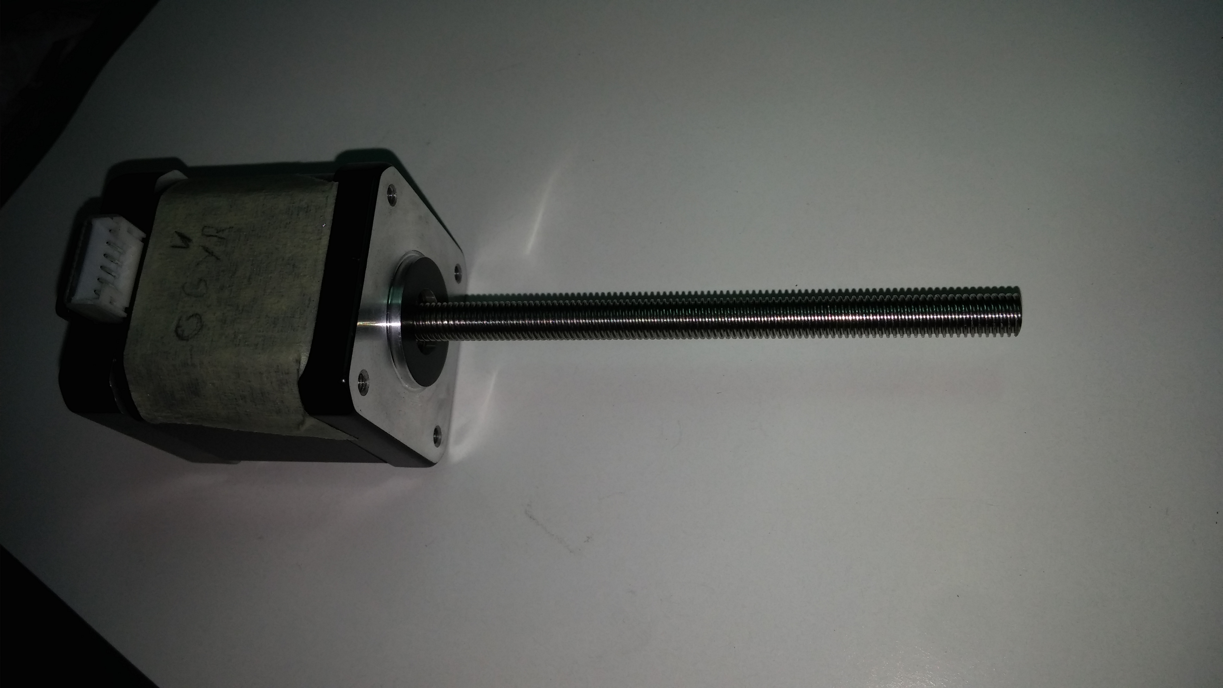
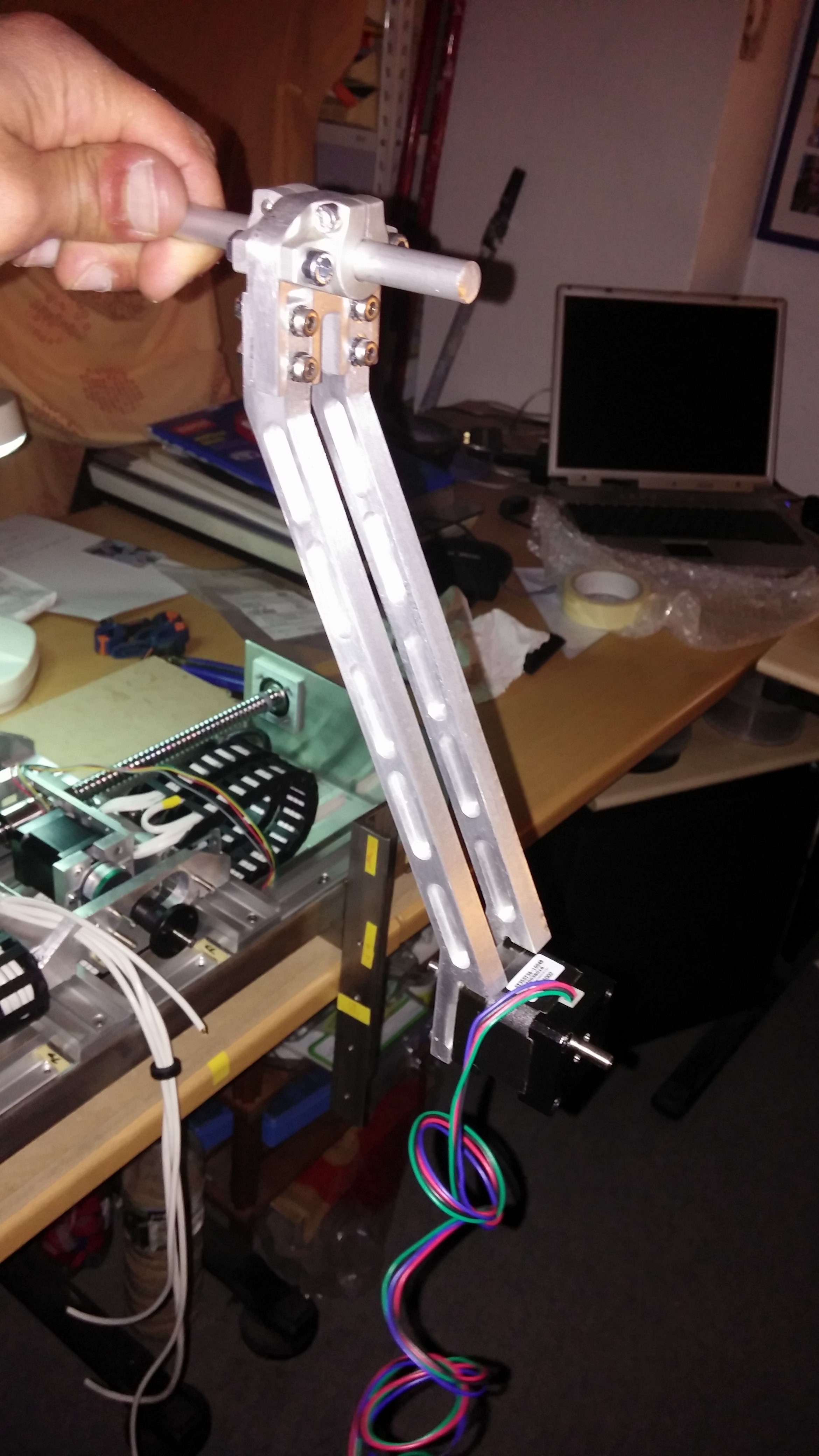
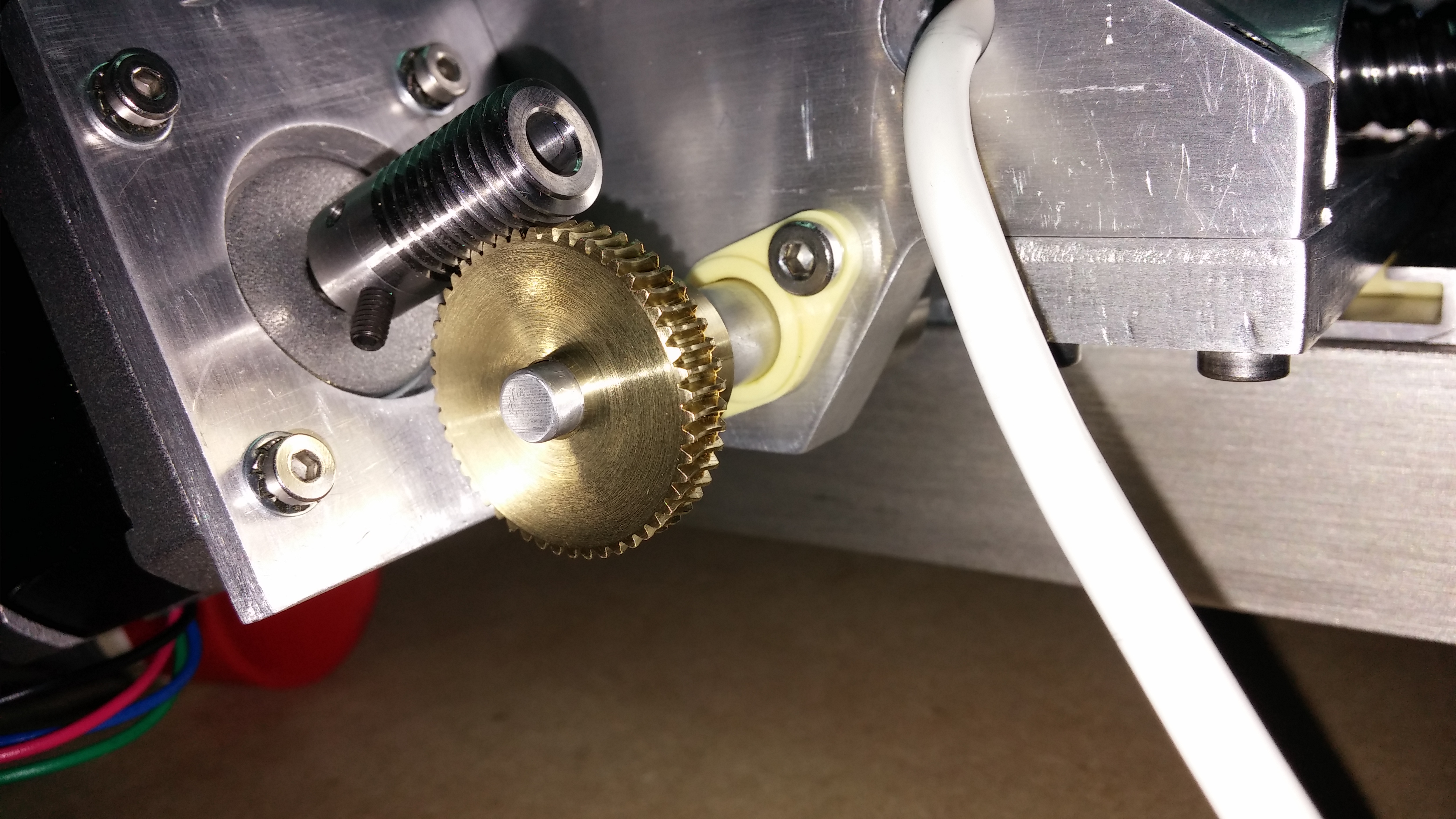
The lower end of the arm attaches directly to the “wrist” motor, making it effectively a key element of its structure. These holes were also carefully marked and drilled.

CAM00289


CAM00291

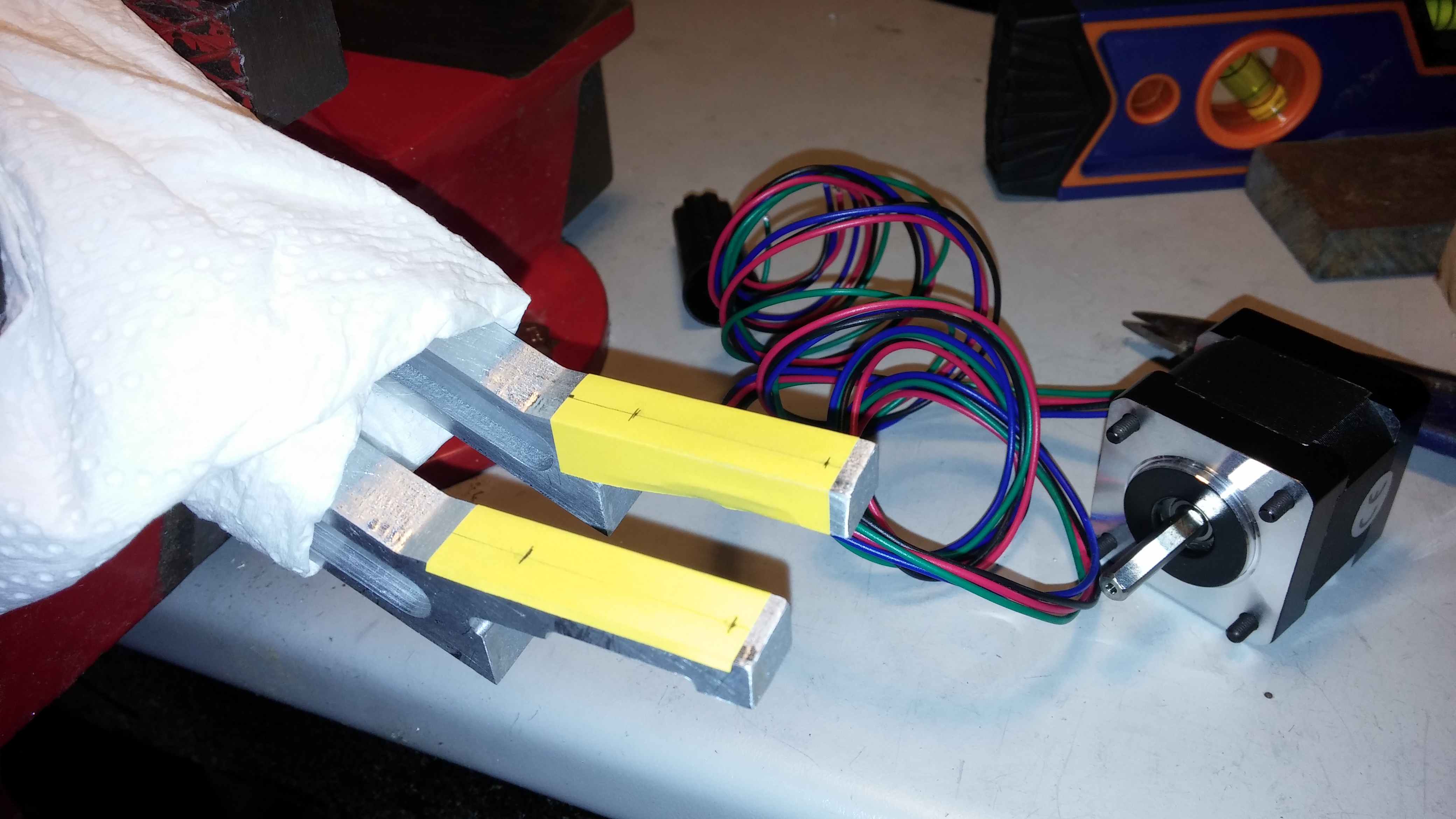
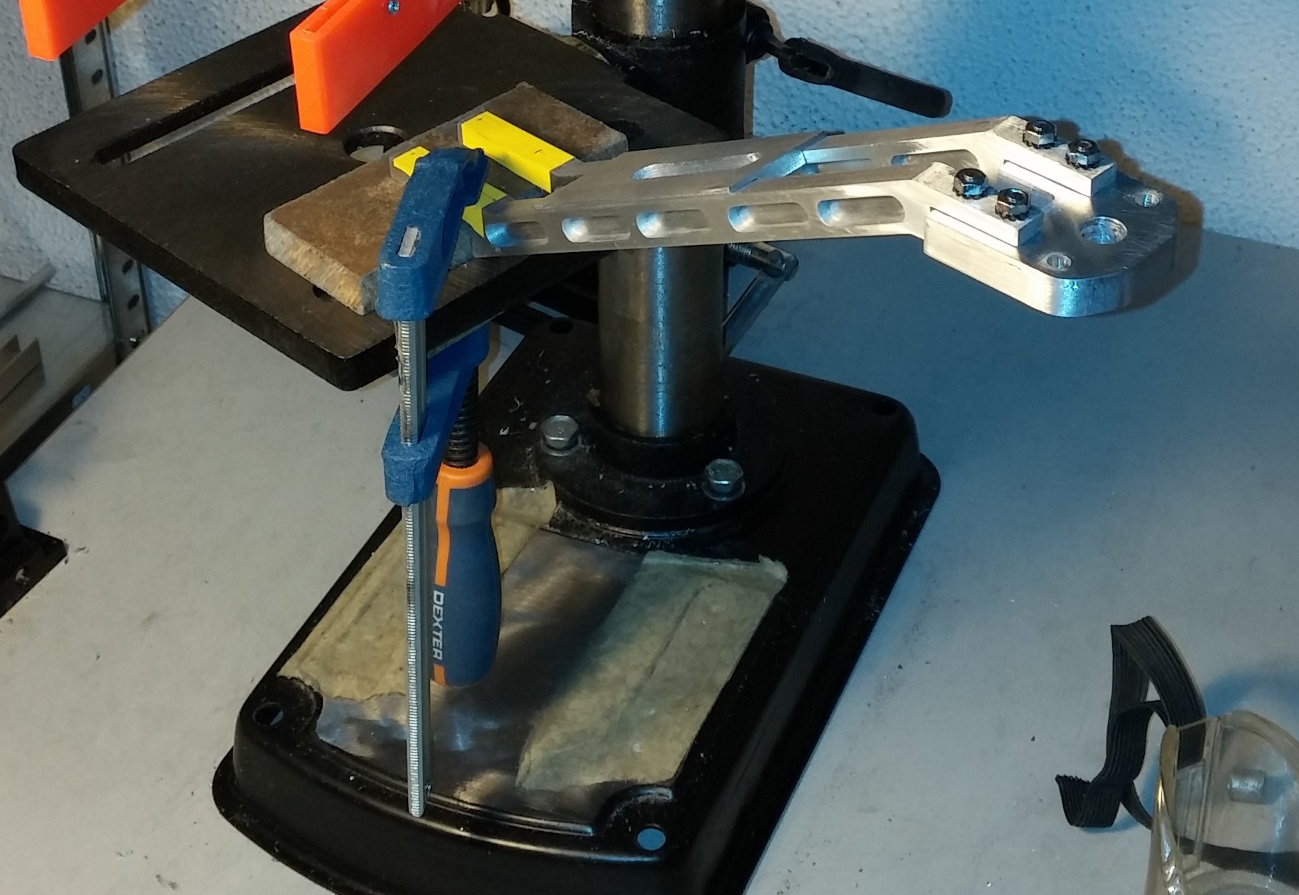
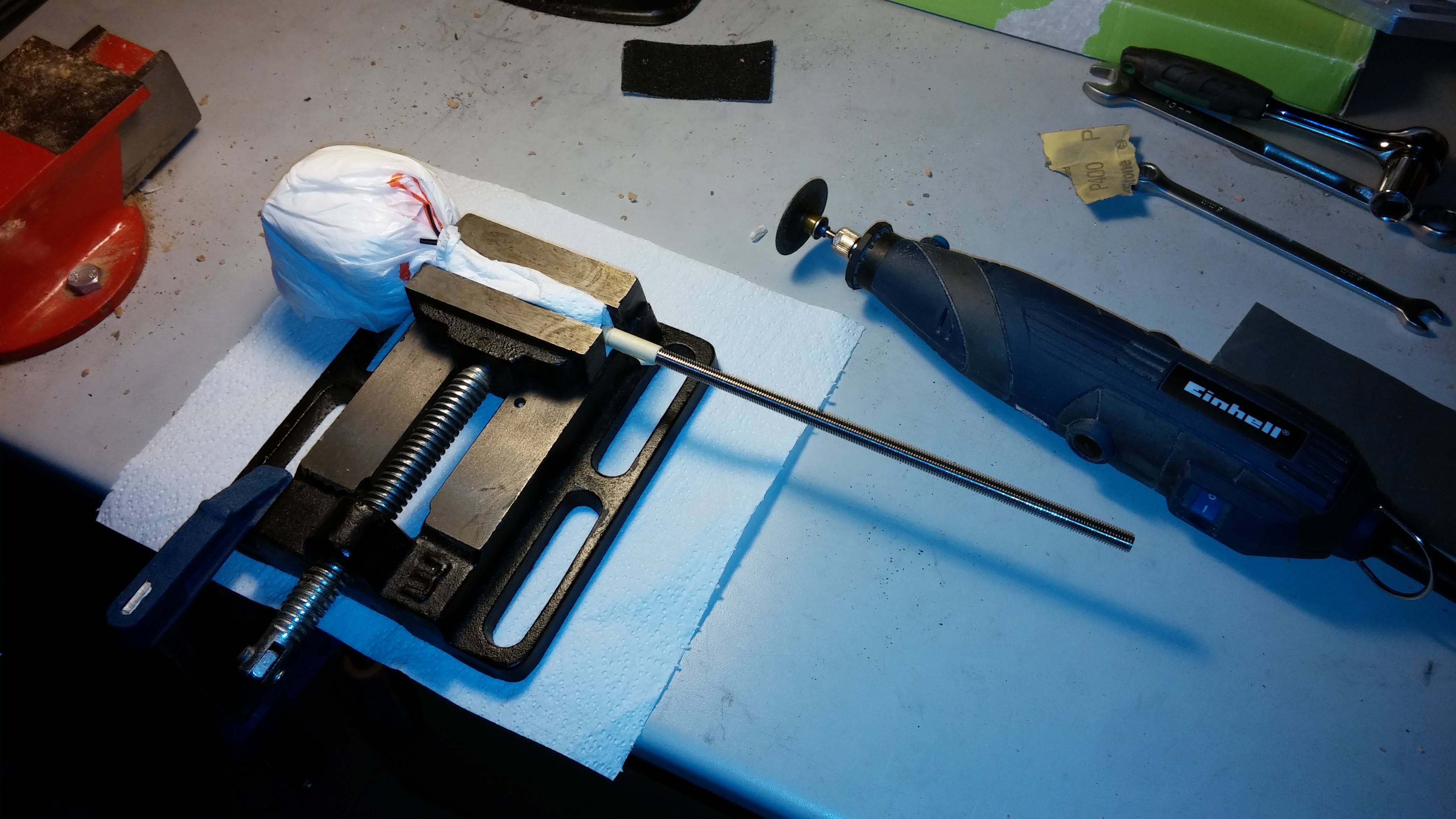
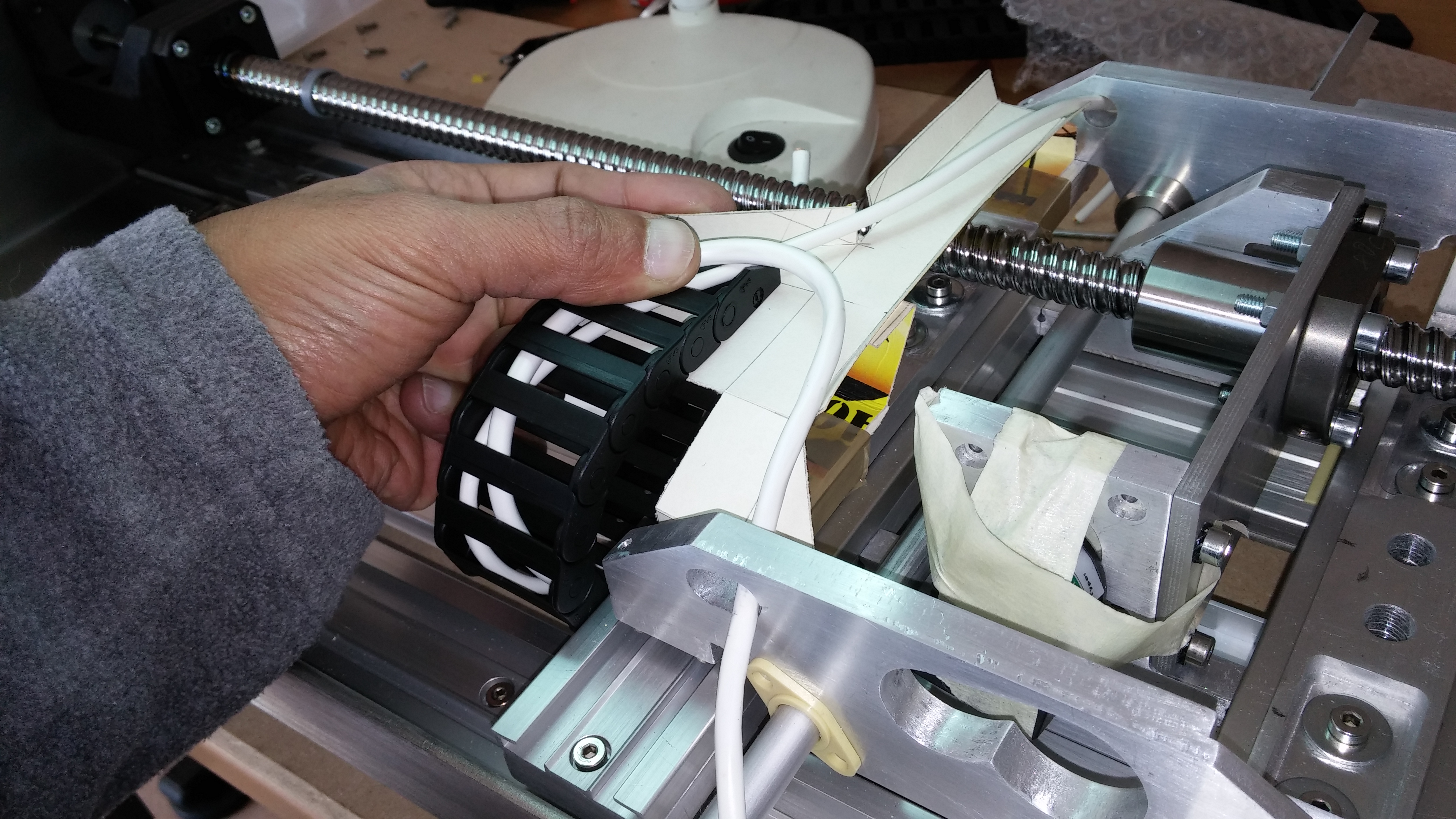
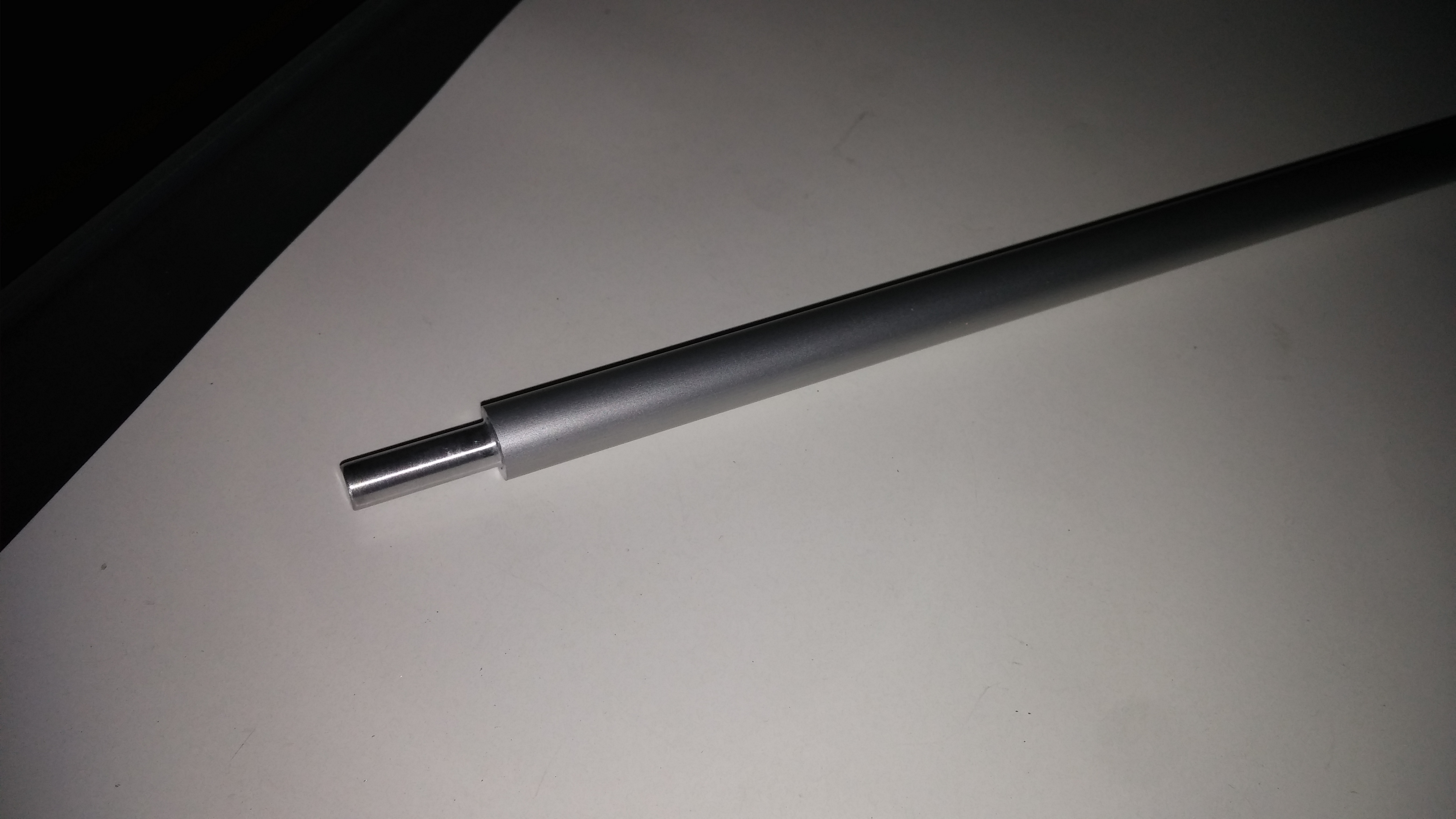
The arm was then temporarily clamped to a dummy shaft to access its overall stiffness.

CAM00285

CAM00284

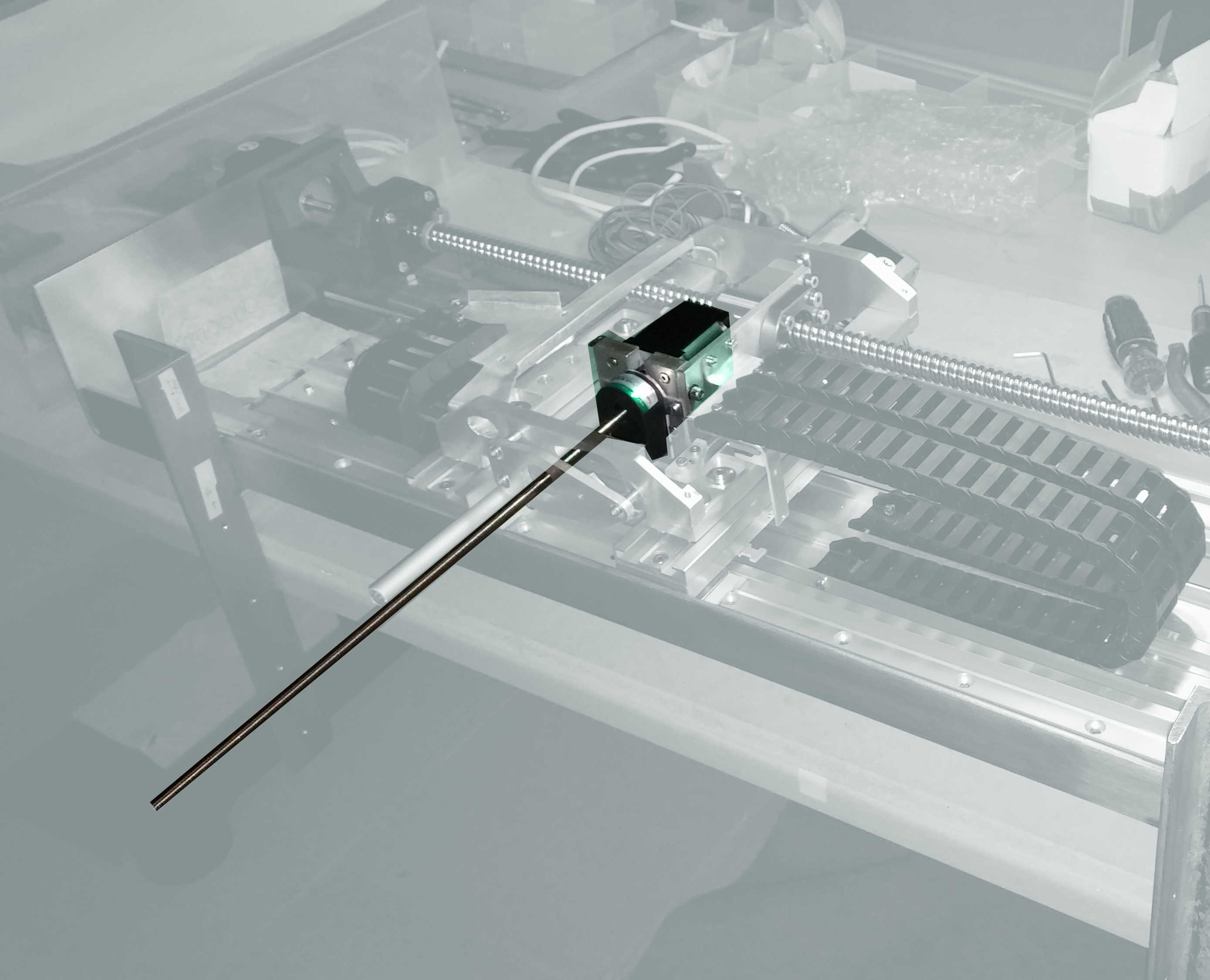
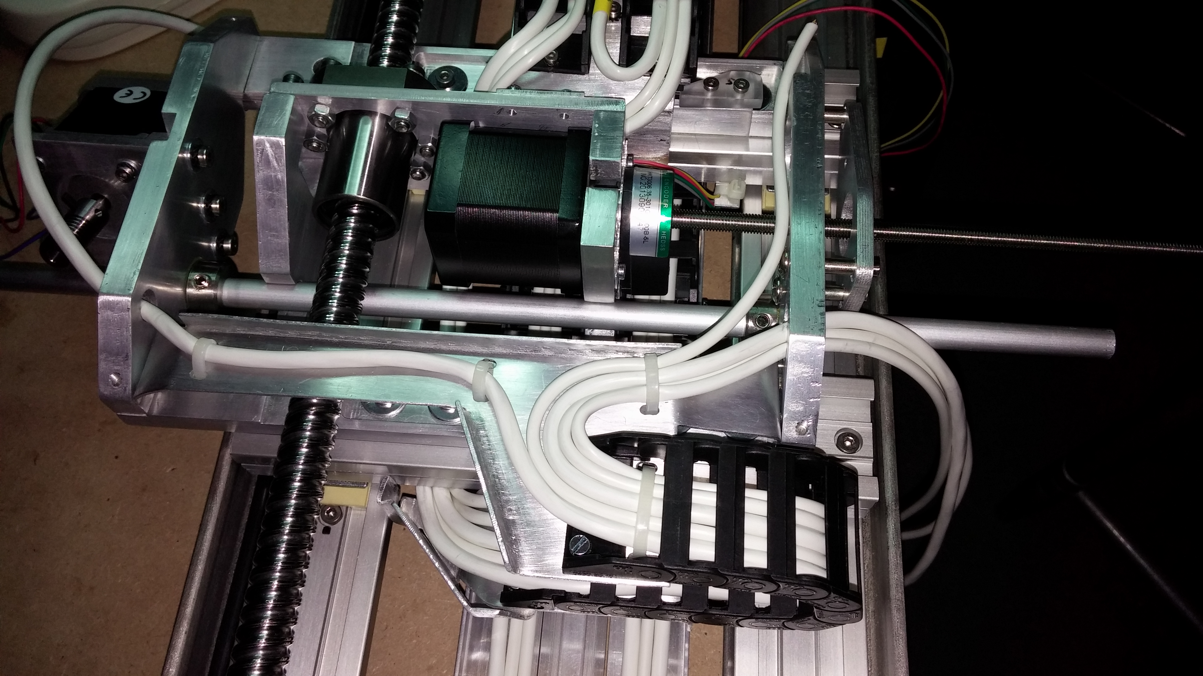
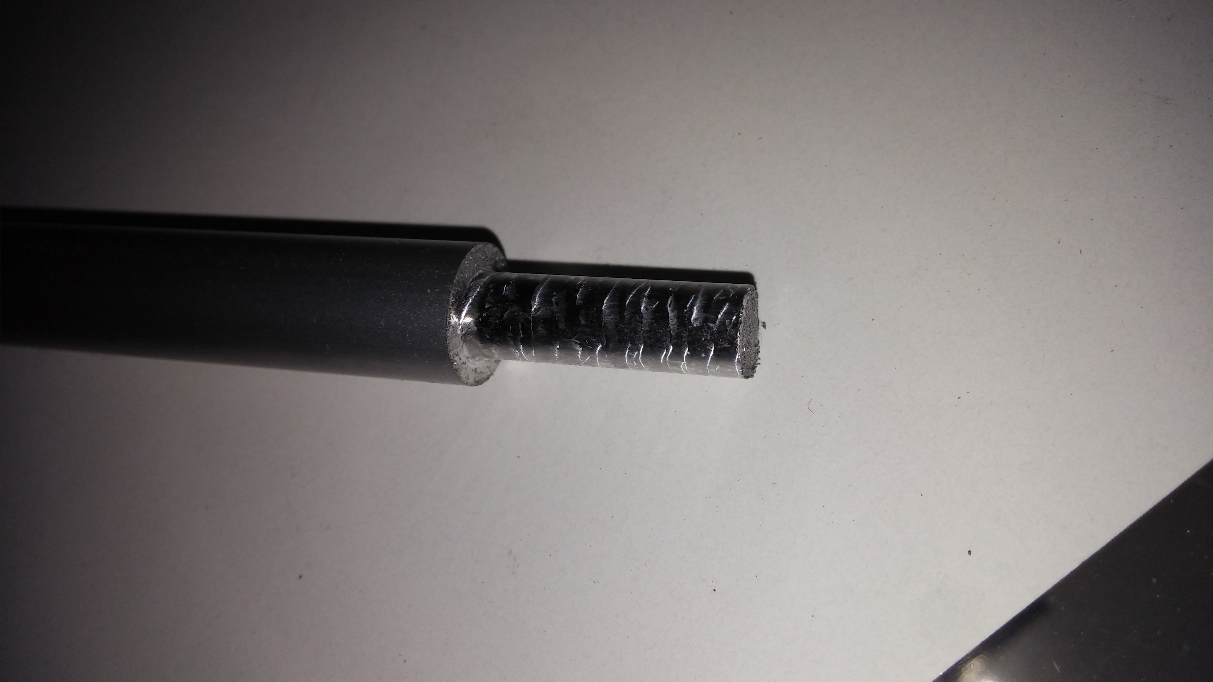
Finally the arm was clamped to the aluminum shaft to test its integration with the robot.

Our tests so far demonstrated that the arm requisites are being met. However the aluminum shaft on which it is clamped has proved to be too flexible causing an unacceptable degree of torsion to the whole assembly.


Aluminum sheet fabrication

There are several parts on the voind robot made from aluminum sheet, most notably the cable supports which route the cables and keep them out of the way of moving parts.

YUpperCableSupport

Although their basic shape and position were defined early in the design, only after initial assembly we were able to determine their correct dimensions and integrate them with the other parts.

We started by creating a cardboard mockup of the part.

CAM00148

This allowed us to check if it would support the cables effectively and the clearances we’d have for driving the screws during assembly and disassembly.

CAM00087

Once we were satisfied with the cardboard mockup we traced the part over 1.5mm aluminum sheet.

CAM00152

Using a Dremel cutting wheel we then cut the part out of the aluminum sheet.

CAM00154

Bending was done manually using a vice and steel guides.

CAM00159

Final tests guided us on tracing the locations of additional features like holes for screws and cables ties.

CAM00170

Finally the part sitting happily in the overall scheme of things and doing exactly what it was designed for.

CAM00232

DIY combined Milling/Lathe machine

The voind robot design is based on a swivel arm that rotates on a horizontal shaft driven by a worm/wheel combination gear. This shaft has a very simple design with a 10mm main section and a 20 mm narrower section with 6mm diameter.

To fabricate the narrower section we decided to build a small combined Milling/Lathe machine from MDF board. This contraption basically holds firmly a small rotating tool with a small drill and at the same time allows a 10mm shaft to be fed and rotated against the mill.

CAM00246

After a quick test we were good to go at machining the end of our aluminum shaft. Check the actual footage below:

After the operation the machined surface shows a scaled aspect due to the manual feeding of the shaft.

CAM00266

But after a quick sanding with fine sand paper the result looks very smooth:

CAM00271

You can see below the wheel firmly clamped to the new shaft and being driven by the worm.

CAM00273

Update:

This aluminum shaft proved to be too much flexible. A steel shaft will have to be used instead.

Cutting a threaded shaft

One of the motors on the voind robot is an External Linear Stepper Motor, more precisely an SY17STH0404-300A6.35X2X2-P1-EX. It has a threaded shaft engaging a threaded nut that drives the robot arm perpendicularly to the equipment face.584[1]

This motor is conveniently supplied with a 30 cm shaft which should be more than enough for every application. However in our case we needed to cut the shaft shorter.

YMotor

We first wrapped the motor in plastic film to protect it from any metal chips and used a small drill press vice to hold it firmly by the shaft, having wrapped it in a generous quantity of soft paper to protect the thread.CAM00251

We then used a Dremel EZ456 cutting wheel to make an initial cut one centimeter outside the mark to be able to position the tool perpendicularly to the shaft for the final cut. To prevent overheating the shaft and motor we cut in 10 to 15 seconds intervals followed by 45 to 60 seconds periods of pause for cooling.

Interestingly, although the shaft seems to be made from stainless steel, not a single spark was produced during the cut…

Ideally we would have a 6.35×2 nut screwed in to help restore any damaged thread start by removing it after the cut. However we did not have any suitable nut around and we had to resort to a magnifying glass and some fine sand paper to make sure the threads started smoothly.CAM00258

Finally the motor with the correct thread length and ready for assembly.CAM00261

First cables installed

We just installed the first cables that will connect the control electronics to the various motors and sensors.

CAM00225

At this stage this is only for checking if all cables are correctly routed and clear any moving parts.

CAM00232

Cabling